


ENFORCER FLUSH-MOUNT LOW-PROFILE UFO CAMERA MANUAL ENFORCER FLUSH-MOUNT LOW-PROFILE UFO CAMERA MANUAL
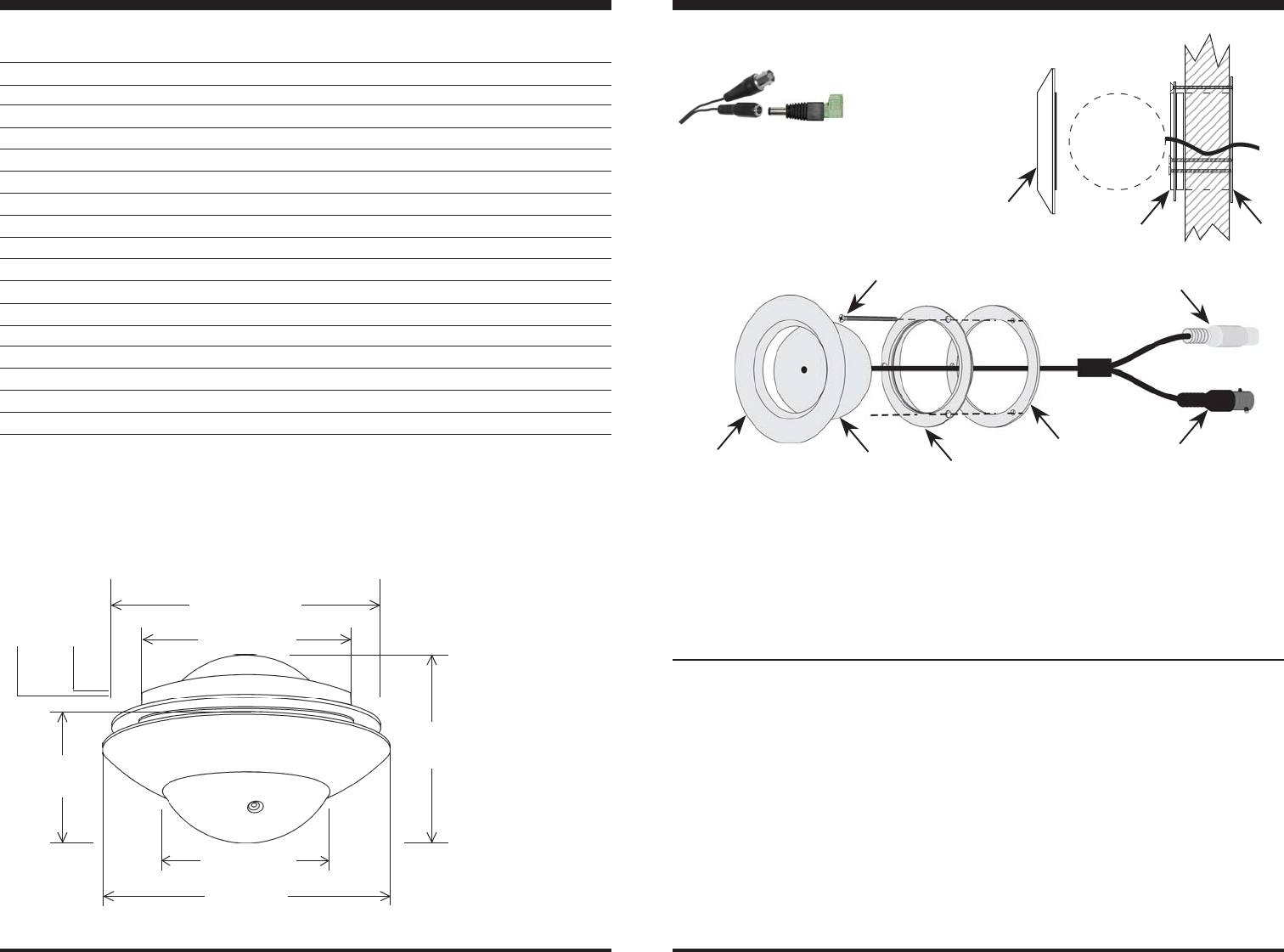
Dimensions:
To BNC
(From DC
camera)
Power cord included. For easy connection of
flush-mount ball or other camera to power supply.
3"
(77mm)
1
15
/
16
"
(49mm)
1"
(26mm)
2
1
/
4
"
(56mm)
2
13
/
16
"
(72mm)
1
/
8
"
(3mm)
1
15
/
16
"
(49mm)
*The EV-122C-FVA3Q incorporates day/night capability. This means that the camera switches to B/W mode at night.
Power adapter
with terminal
block
Parts List
1 x Flush-Mount camera
1 x Flange
1 x Base
1 x Ring bracket
3 x Mounting screws
1 x Manual
BEFORE STARTING
1. Please read this manual carefully and keep it for future
reference.
2. Use the camera within given temperature and electrical limits.
3. Do not mount the camera where it is exposed to rain or other
moisture, or in humid or dusty places.
4. Do not point the camera at the sun. Heat could damage the
camera, even when not in use.
5. Do not mount the camera in areas exposed to radiation, strong
INSTALLATION
1. Run a 12VDC power supply wire and a video cable with a
male BNC connector to the wall or ceiling where the
camera is to be mounted.
2. Temporarily connect the camera to the 12VDC power
supply.
3. Temporarily connect the camera’s female BNC connector
to the video cable’s male BNC connector.
4. While watching the monitor, hold the camera against the
wall or ceiling by hand where it is to be mounted, then turn
the camera until it is certain that this mounting location is
correct. Use a pencil to mark the location.
5. Disconnect the 12VDC power supply and video cable.
6. Drill a 2
1
/
4
” (56mm) hole in the ceiling or wall where the
camera is to be mounted.
magnetic fields, or strong electrical signals.*
6. Do not open or disassemble the camera. There are no user-
serviceable parts inside.
7. Do not drop the camera or subject it to strong vibrations.
* Note: Many video monitors produce strong electromagnetic
fields close to the display CRT, especially when the monitor is
turned on or during de-Gaussing, which occurs automatically
with many monitors when the monitor is turned on.
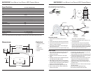
7. Twist the flange off the base and remove the camera ball.
8. Place the ring bracket behind the hole.
Note:
Ring bracket is not necessary if mounting directly to wall.
9. Push the base into the hole, and secure to the ring bracket
using the three supplied machine screws.
10.Run the power supply and video cable through the wall or
ceiling to the hole, and through the bracket and base.
Connect to the camera’s power and video connectors.
11.Hold the ball in the base, and secure with the flange. Do
not tighten securely.
12.Apply power to the camera. Watch the monitor and adjust
the angle of the lens.
13.Secure the camera by tightening the flange.
14.Do a final test of the video camera and monitor.
Type
Chip
Resolution
Pickup elements
Sync
Video output
Lens (F2.5)
Minimum illumination
Shutter control
Gain control
Gamma correction
White balance
S/N ratio
Power source
Current consumption
Ambient temperature
Dimensions
EV-122C-FVA3Q (NTSC)
Mini Flush-Mount Low-Profile UFO Camera
1/3" Sony Super HAD CCD
420 TV lines
510(H) x 492(V) effective pixels
Internal
1 Vp-p composite output, 75 Ohms.
3.7 mm
B/W 0.05 lux (day/night)*
Auto Electronic Shutter (AES), 1/60~1/100,000 sec.
Auto
0.45
Auto
>48dB
12 VDC
130mA±10mA
-4
o
~ 122
o
F (-20
o
~50
o
C)
1
15
/
16
" x 3" (49 x 77 mm)
Specifications
Camera ball
Base
Ring bracket
(inside the
ceiling/wall)
Flange
BNC
Connector
Power
Connector
Screws (x 3)
Wall or
ceiling
Base
Ring
bracket
Camera
ball
Flange