


ENFORCER 24 LED CCD IR DAY/NIGHT CAMERA MANUAL ENFORCER 24 LED CCD IR DAY/NIGHT CAMERA MANUAL
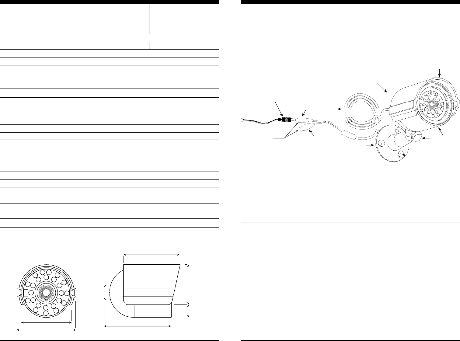
Dimensions:
Color camera
NTSC
1/3” CCD, Sony
420 TV lines
512 x 492 pixels (NTSC) , 512 x 582 pixels (PAL)
2:1 interlace
Internal
1V pp composite output, 75 ohms
EV-132C-DWL6Q / EV-135C-DWL6Q (6mm) ; EV-132C-DWL8Q / EV-135C-DWL8Q (8mm)
EV-132C-DWLDQ / EV-135C-DWLDQ (12mm) ; EV-132C-DWLHQ / EV-135C-DWLHQ (16mm)
EV-132C-DWL6Q / EV-135C-DWL6Q (53
o
) ; EV-132C-DWL8Q / EV-135C-DWL8Q (39
o
)
EV-132C-DWLDQ / EV-135C-DWLDQ (26
o
) ; EV-132C-DWLHQ / EV-135C-DWLHQ (19
o
)
0.1 lux (LEDs off), 0 0 lux (LEDs on)
0.45
>50dB (AGC off)
Auto Electronic Shutter (AES) 1/60 (1/50)~1/100,000 sec.
auto
auto
IP68 weatherproof
24
Approximately 80’ (25m)
12VDC±10%
100mA (IR off), 360mA (IR on)
14°~131° F (-10°~55° C)
3
1
/
16
”(L) x 2
1
/
4
”(D) (78 x 57 mm) (without sunshield)
16 oz. (454g)
BEFORE STARTING
1. Please read this manual carefully and keep it for future reference.
2. Use the camera within given temperature and electricity limits.
3. Do not aim the LED light directly at the eyes when the LEDs are on.
4. Do not point the camera at the sun. Heat could damage the
camera, even when not in use.
5. Do not mount the camera in areas exposed to radiation, strong
magnetic fields, or strong electrical signals.*
INSTALLATION
1
. Run a 12VDC power supply wire and a video cable with a male
BNC connector through the wall to where the camera is to be
mounted (if necessary).
2. Assemble the mounting bracket; then screw it into the back of the
camera. Make sure the mounting base is tightened to the bracket.
3. Temporarily connect the camera to the 12VDC power supply. Do
not cut DC jack or video jack as warranty will be voided. Use
the included SECO-LARM’s pigtail connector.
4. Temporarily connect the camera’s female BNC connector to the
video cable’s male BNC connector.
5. While watching the monitor, hold the camera bracket against the
wall by hand where it is to be mounted, then twist the camera until
it is certain that this mounting location is correct. Use a pencil to
mark the location of the three screw holes in the bracket.
6. Disconnect the 12VDC power supply and video cable.
6. Do not open or disassemble the camera. There are no user-
serviceable parts inside.
7. Do not drop the camera or subject it to strong vibrations.
* Note: Many video monitors produce strong electromagnetic fields
close to the display CRT, especially when the monitor is turned
on or during de-Gaussing, which occurs automatically with many
monitors when the monitor is turned on.
7. Mount the bracket to the wall using the three included mounting
screws. If the wall is made of dry wall, brick, or similar material, it
may be necessary to use the three included screw anchors.
8.
Reconnect the 12VDC power supply and video cable. Turn the monitor
on, and make sure the camera is sending the proper video signal.
9. Adjust the camera angle:
(a) Loosen and tighten the bracket’s thumb screw to turn the
camera and change its angle relative to the bracket. This
ensures the camera is pointing in the right direction.
(b) Loosen and tighten the adjustment plate to rotate the camera
on its axis. This rotates the angle of the video image.
10.Tighten the bracket’s thumb screw and the adjustment plate so
that the camera does not move, but not so tight that it cracks the
case or bracket.
11.Do a final test of the video camera and monitor.
Type
Video format
Chip
Resolution
Pickup elements
Scanning system
Sync
Video output
Lens
Viewing angle
*
Minimum illumination
Gamma correction
S/N ratio
Shutter control
Backlight compensation
Automatic gain control (AGC)
Enclosure
# of infrared LEDs
Max. LED range
Power source
Power consumption
Operating temperature
Dimensions
Weight
Specifications
2
1
/
4
” (57mm)
2
11
/
16
” (68mm)
1
13
/
16
” (46mm)
9
/
16
” (14.5mm)
3
1
/
16
” (78mm)
2
9
/
16
” (65mm)
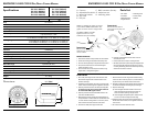
A. Camera
B. Adjustable Sunshield
C. Mounting bracket
D. 36” cord
E. DC jack
F. BNC connector (female)
G. Adjustment nut
H. Mounting holes
®
Infrare d
Day/Night
ENFORCER
ENFORCER
®
I fraed
Day N g t
A
G
B
Hx3
EV-135C-DWL6Q
EV-135C-DWL8Q
EV-135C-DWLDQ
EV-135C-DWLHQ
PAL
EV-132C-DWL6Q
EV-132C-DWL8Q
EV-132C-DWLDQ
EV-132C-DWLHQ
* All viewing angles are approximate
C
D
E
Important:
Do not remove label or
open case as warranty will
be voided.
F
Important:
Do not cut DC Jack (E) or
Video Jack (F) as warranty
will be voided.
Use SECO-LARM’s included
Pigtail Connector for easy
installation and serviceability.
NOTE: For additional pigtail connectors,
inquire SECO-LARM’s EVA-F5521-3Q
pigtail connector with 3-ft. length cable.
Parts List
1 x IR camera
1 x Sunshield
1 x Mounting bracket
1 x Pigtail connector
3 x Mounting screws
3 x Screw anchors
1 x Manual