


ENFORCER Color Hi-Res IR Bullet Camera Manual ENFORCER Color Hi-Res IR Bullet Camera Manual
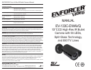
Dimensions:
3
7
/
16
” (88mm)
3
13
/
16
” (97mm)
5
9
/
32
” (134mm)
3
15
/16” (100mm)
9
7
/8” (251mm)
3
7
/
16
” (88mm)
3
11
/
16
” (68mm)
Parts List:
1 x Camera with bracket
1 x Mounting plate
1 x Sunshield
4 x Mounting screws
4 x Hex screws
1 x L-wrench
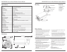
Mounting plate
Camera base
Hex screws
Mounting screws
Focus
Zoom
Sunshield
______________________________________________________________________________________________________________
______________________________________________________________________________________________________________
______________________________________________________________________________________________________________
______________________________________________________________________________________________________________
______________________________________________________________________________________________________________
______________________________________________________________________________________________________________
______________________________________________________________________________________________________________
______________________________________________________________________________________________________________
____________________________________________________________________________________________________________________________________________________________________________________________________________________________
______________________________________________________________________________________________________________
______________________________________________________________________________________________________________
______________________________________________________________________________________________________________
______________________________________________________________________________________________________________
______________________________________________________________________________________________________________
______________________________________________________________________________________________________________
______________________________________________________________________________________________________________
____________________________________________________________________________________________________________________________________________________________________________________________________________________________
______________________________________________________________________________________________________________
______________________________________________________________________________________________________________
______________________________________________________________________________________________________________
______________________________________________________________________________________________________________
______________________________________________________________________________________________________________
______________________________________________________________________________________________________________
Type
Chip
Resolution
Pickup elements
Scanning system
Sync
Video output
Lens
IR LEDs
IR distance
Minimum illumination
Gamma correction
S/N ratio
CDS sensor
Shutter control
Backlight compensation
Gain control
White balance
Power source
Power consumption
Storage temperature
Operating temperature
Dimensions
Weight
Color camera
1/3” Sony Super HAD CCD
550 TV lines
768 x 494 pixels
NTSC 2:1 interlace
Internal
1V pp composite output, 75 ohms
DC Auto Iris, Varifocal 4mm ~ 9mm, F1.6
56 IR LEDs
Up to 100’ (30m)
0.1 lux (IR off), 0 lux (IR on)
0.45
More than 50dB
Photoconductive cells, 10 lux, Resistance 5~10k ohm
Auto
Off
Auto
Auto
12VDC/24VAC (dual voltage)
700mA max. (IR on)
-4°~140° F (-20°~60° C), humidity 95% max.
14°~122° F (-10°~50° C), humidity 95% max.
3
15
/16” x 5
9
/32” x 9
7
/8” (100 x 134 x 251 mm)
3lb., 5oz. (1,500g)
Specifications:
Mounting:
Before Starting
1. Please read this manual carefully and keep it for future reference.
2. Use the camera within given temperature and electrical limits.
3. Do not mount the camera where it is exposed to rain or other
moisture, or in humid or dusty places.
4. Do not point the camera at the sun. Heat could damage the
camera, even when not in use.
5. Do not mount the camera in areas exposed to radiation, strong
magnetic fields, or strong electrical signals.*
6. Do not open or disassemble the camera. There are no user-
serviceable parts inside.
7. Do not drop the camera or subject it to strong vibrations.
* Note: Many video monitors produce strong electromagnetic
fields close to the display CRT, especially when the monitor is
turned on or during de-Gaussing, which occurs automatically
with many monitors when the monitor is turned on.
Installation
1. Run a 12VDC or 24VAC power supply wire and a video cable
with a male BNC connector through the wall to where the
camera is to be mounted.
2. Temporarily connect the camera to the power supply.
3. Temporarily connect the camera’s female BNC connector to the
video cable’s male BNC connector.
4. While watching the monitor, hold the camera against the wall or
ceiling by hand where it is to be mounted, then turn the camera
until it is certain that this mounting location is correct. Use a
pencil to mark the location of the four screw holes in the
mounting plate.
5. Disconnect the power supply and video cable.
6. Mount the mounting plate to the wall or ceiling using the four
included mounting screws. If the wall is made of dry wall, brick,
or similar material, it may be necessary to use screw anchors
(not included).
7. Mount the camera base to the mounting plate using the four
included hex screws.
8. Reconnect the power supply and video cable. Turn the monitor
on, and make sure the camera is sending the proper video
signal.
9. Adjust the camera angle.
10.Put the sunshield on the camera.
11. Do a final test of the video camera and monitor.