


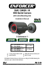
ENFORCER DNR / DWDR / IR NVD Bullet Camera with 4-Axis Mounting Arm
SECO-LARM U.S.A., Inc. 3 3 SECO-LARM U.S.A., Inc. 33 3
1. Please read this manual carefully and keep it for
future reference.
2. Use the camera within given temperature and
electrical limits.
3. Do not aim the LEDs directly at the eyes when the
LEDs are on.
4. Do not point the camera at the sun. Heat could
damage the camera, even when not in use.
5. Do not mount the camera in areas exposed to
radiation, strong magnetic fields, or strong
electrical signals.
6. Do not open or disassemble the camera. There are
no field-serviceable parts inside.
7. Do not drop the camera or subject it to
strong vibrations.
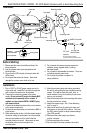
1. Run a 12VDC or 24VAC power supply wire and a
video cable with a male BNC connector through the
wall to where the camera is to be mounted.
2. Temporarily connect the camera to the power
supply. Do not cut the DC jack or the female BNC
connector as the warranty will be voided. If
needed, use the included SECO-LARM DC plug
with terminal block.
3. Connect the included service monitor port connector
to the service monitor port.
4. Connect the service monitor port connector’s BNC to
a test monitor.
5. While watching the monitor, hold the camera against
the wall or ceiling by hand where it is to be mounted,
then turn the camera until it is certain that this
mounting location is correct. Use a pencil to mark
the location of the four screw holes in the
mounting plate.
6. Mount the mounting plate and rubber grommet to
the wall or ceiling using the four included mounting
screws. If the wall is made of drywall, brick, or
similar material, it may be necessary to use screw
anchors (not included).
7. Mount the camera base to the mounting plate using
the four included hex screws.
8. Adjust the camera angle. See “4-Axis Mounting
Arm” on page 2.
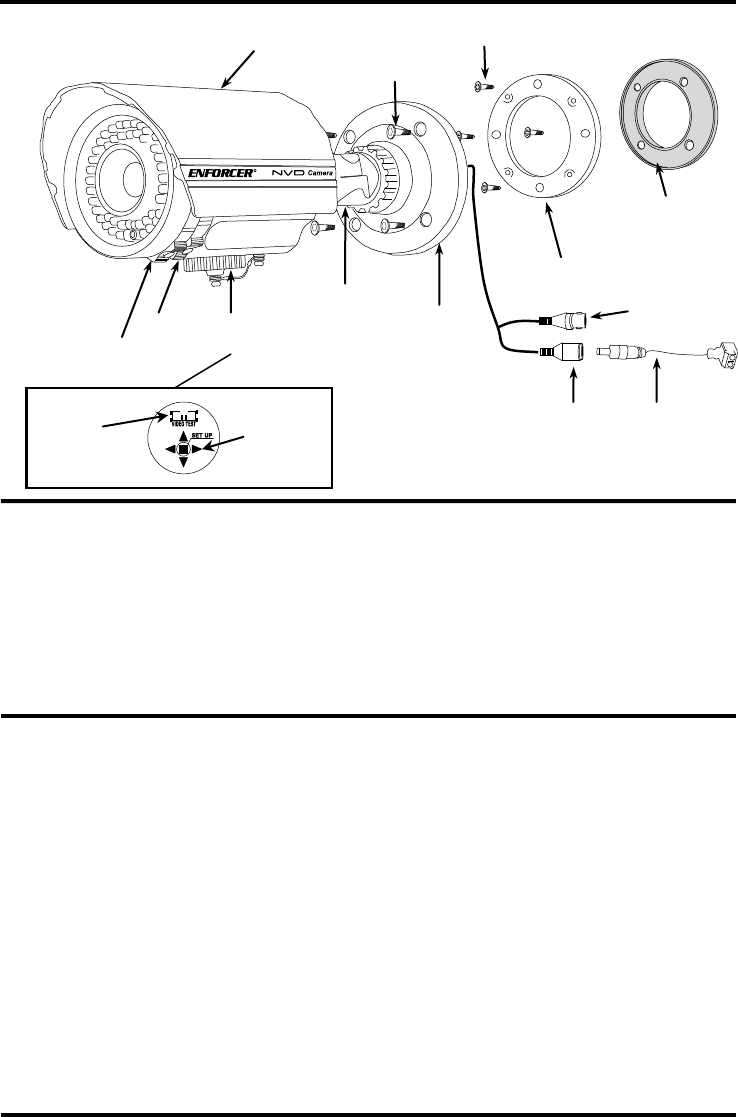
9. Adjust zoom and focus by moving the zoom and
focus knobs on the side of the camera. Then use
the OSD control joystick to adjust camera settings.
(See OSD manual).
10. Disconnect the power supply and service
monitor connector.
11. Put the sunshield on the camera.
12. Do a final test of the video camera and monitor.
Installation:
Before Starting:
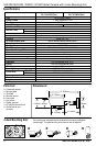
Focus
4-Axis mounting arm
Mounting base
Sunshield
Rubber grommet
Service
monitor port
Zoom
OSD joystick
Connect
service monitor
port connector
Mounting plate
DC Jack
BNC connector
DC plug with
terminal block
Important:
Do not cut DC jack or BNC
connector as warranty will be voided.
Hex screw
Overview:
Mounting screw