


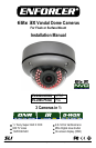

Elite 3X Vandal Dome Cameras
SECO-LARM U.S.A., Inc. 3 SECO-LARM U.S.A., Inc. 33 3
1. Please read this manual carefully and keep it for future
reference.
2. Use the camera within given temperature and electrical
limits.
3. Do not aim the LEDs directly at the eyes when the LEDs
are on.
4. Do not point the camera at the sun. Heat could damage
the camera, even when not in use.
5. Do not mount the camera in areas exposed to
radiation, strong magnetic fields, or strong electrical
signals.
6. Do not open or disassemble the camera. There are no
field-serviceable parts inside.
7. Do not drop the camera or subject it to strong
vibrations.
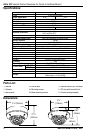
Before Starting:
Installation:
Overview:
1. Run hidden cables from the video source and power
supply and connect to the camera. Do not cut the DC
jack or female BNC connector as this will void the
warranty. If needed, use the included SECO-LARM
DC plug with terminal block.
2. Test the voltage from the power supply.
Use 12VDC or 24VAC.
3. Undo the hex screws on the side of the dome using the
included allen wrench and remove the dome and the
rubber ring from the camera and base.
4. For surface mounting:
Hold the camera against the wall, ceiling, or other
mounting surface while watching the monitor to find the
best mounting location. Mark that location with a
pencil. Mount the base to the wall or ceiling using the
four included mounting screws. If the wall is made of
brick, drywall, or similar material, it may be necessary
to use screw anchors (not included).
Mount the camera to the base using the base-mounting
screws.
For flush mounting:
Use the included mounting template as a guide to
drill the necessary holes. Insert the camera into
the hole. Mount the camera to the wall using the
four included mounting screws.
5. Adjust the camera angle as needed. Use the
OSD control joystick to adjust the camera settings
(See the OSD manual). Connect a service
monitor to the service monitor port connector for
on-site adjustments.
6. To adjust zoom and focus, loosen the lock knobs
by hand or with a screwdriver. Slide left or right to
adjust. Do not use power tools. Lens damage
may result
7. Replace the rubber ring on the camera.
8. Reattach the dome to the camera.
9. Use the included allen wrench to tighten the set
screw, securing the dome to the base.
10. Do a final test of the video camera and monitor.
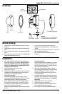
Important:
Do not cut the DC jack or the female BNC
connector as this will void the warranty.
DC Jack
DC Plug to
terminal block
Service
monitor port
OSD joystick
Dome
Rubber ring
Camera
Base
(For surface mounting only)
BNC
connector
Set screw