


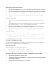
CONTROLS IN DETAIL
1. SHUTTER RELEASE LEVER- pulling the shutter release lever back part way activates the camera meter and
autofocus. Pulling the lever back all the way fires the camera.
2. MAIN DIAL KNOB: It rotates clockwise and counter clockwise. It can be use alone or in combination with other
controls to select or set various camera functions or modes
Refer to your camera manual.
3. MODE DIAL KNOB: Rotate to change the exposure mode (P, S, A, M) and different shooting modes .
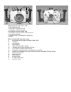
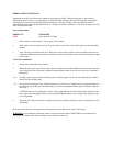
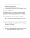
2. HOT SHOE CONNECTOR- connects the camera to the Flash Bulkhead. Slide this Connector into the camera Hot
Shoe. When detaching do not pull the cord as this might damage the electrical connections.
3. FOCUS/ZOOM PINION GEAR- engages and operates the focus or zoom gear on the lens.
4. BULKHEAD CONNECTOR- for Flash Sync Cord. (Nikonos Type 5 pins).
5. EXTRA CONNECTOR (optional) - allows for installation of a second flash bulkhead.
6. FOCUS/ZOOM KNOB- turning allows manual focus of a single focus lens or zoom of a zoom lens.
7. STROBES ARMS ATTACHMENTS (optional) - allows the installation of strobe arms.
8. GRIPS- attached to each side of the housing to provide ease and comfort of handling
9. MOUNTING HOLE- these are 1/4-20 TPI holes that are ready to accept TLC Base Brackets or TLC Base Ball for
strobe arms or accessories.
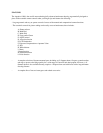
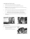
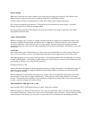
11. VIEWFINDER: A full view of the illuminated camera viewfinder displays all necessary information.
12. TOP WINDOW – permit visual contact with Mode Dial
13. AE/FE LOCK CONTROL KNOB – screw in the knob to lock-in the AE/FE function.
14. AF POINT SELECTOR – press to select autofocus point
15. LCD PANEL ILLUMINATOR – press to illuminate rear panel LCD.
16. EXPOSURE COMPENSATION / APERTURE VALUE KNOB – screw in knob to engage exposure
compensation or aperture value selection in manual or aperture priority mode.
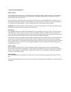
17. CROSS KEYS BUTTONS ASSEMBLY: These buttons have multiple uses. They allow the selection of the focus
area, in the menu mode; they are used to scroll up or down and left to right to choose from your menu selection they
are used in the delete mode and for the manual selection of ISO speed and white balance.
18. REAR LCD WINDOW: allow viewing of camera setting and images taken with the camera.
19. MENU BUTTON: push to allow access to menu.
20. INFO BUTTON: allow viewing of image’s shooting information.
21. JUMP BUTTON: press to allow the navigation between images.
22. PLAYBACK BUTTON: press to view image taken with camera.
23. ERASE BUTTON: press to engage the image deleted function