


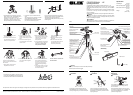

Bubble Levels
Two bubble levels are built-in for vertical and
horizontal positioning.
Changing the camera mounting screw
1. Both 1/4" and 3/8" camera mounting screws
are supplied.
The screw not in use is stored in the side of
the camera platform.
2. Remove the camera mounting screw through
the large end of the mounting track.
It’s a good idea to tighten the camera locking
knob when a camera is not attached to pre-
vent loss of the mounting screws.
Attaching a Camera
1. Hold the camera firmly, and turn the camera
mounting screw to engage the threads.
2. Lock the camera tightly with the knurled
camera locking knob.
3. Tilting the head forward makes it easier to
attach the camera.
Attaching the head to the center column
Loosen the panning lock knob and rotate the base of the head clockwise
to screw it tightly onto the center column.
Tighten the panning lock knob and turn the head clockwise, using both
handles, to tighten as much as possible.
Unlock the panning lock knob for easy panning.
Lock the panning lock knob tightly, then grasp the pan handle and turn
the head counter-clockwise to loosen.
Then loosen the panning lock knob and it will be easy to unscrew the
head by rotating the base of the head counterclockwise.
Removing the head from the center column
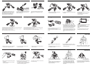
The pan handles are installed as shown with
the long handle on the left, for pan and tilt
movement; the short on the right, for vertical
tilt. If you prefer to have it the other way
around, the tripod will function perfectly.
Install the pan handles
The vertical & tilt handle can be reset inside the
pan & tilt handle by screwing from rear of the
handle as shown here.
The head is installed by screwing it onto the
center column’s 3/8" threaded post socket
hole.
Attach the head
Positioning the elevation
control handle
Raise the elevation control handle into position
by pulling out on the knob to lock it into place.
Operating the center column
1. The center column can be moved up and
down by turning the elevation control han-
dle.
The center column tension adjustment knob
adjusts the tightness of the column and
helps prevent vibration.
2. The worm gear column adjustment mecha-
nism will not move even if pressure is placed
on the head with the tension adjustment
knob unlocked. Note-the column can be
moved, with the elevation control handle,
even when the tension adjustment knob is
fully locked.
Lower center column
tension adjustment nut
The lower center column tension adjustment
nut is used when necessary to adjust the tight-
ness of the center column.
Lower Center Column Tension
Adjustment Nut
Extending legs
1. Release the leg locks by rotating one half
turn.
Because leg are grooved, the leg locks can
be released in any order.
2. The second section, form the top, in each
leg has reference marks every 10 cm for pre-
cise height adjustment.
Three-position adjustable legs
1. When opening each leg, it will stop at the
first (standard) position. To change the angle
of each leg, move the leg a little closer to the
center column and pull the leg angle adjust-
ment lock out one click. The leg will be
released and can be opened to the second
position. To move to the third position, again
pull the leg angle adjustment lock out one
click.
2. After choosing the desired leg angle, secure-
ly push in the adjustment lock.
When all legs are opened fully, the lowest
position is 585 mm (23 1/12") from the
ground.
An optional short center column* permits
shooting as low as 370 mm (14 7/12").
Panning guide
A rotating scale at the base of the head makes
it easy to set exact shooting angle.
To begin, set the mark at the base of the head
on “0”.
585 mm
(23 1/12")
Using the pan head
1. Loosen the panning handle, and the head
will move freely front to rear.
2. Loosen the panning lock knob, and the head
will rotate.
3. Loosen the vertical tilt handle and the level
can be adjusted.
The pan head is specially lubricated for
smooth movement.