Location and Function of Parts
5
Location and Function of Parts
Front and Right Side
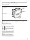
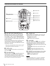
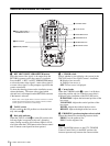
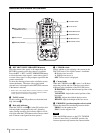
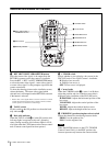
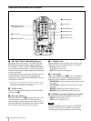
a Camera connector (PRO 76-pin DIGITAL)
Connects to the camera’s 76-pin connector.
b POWER switch
Turns this unit’s power supply on and off.
To power the unit, set the switch to EXT or CCU
according to the type of power source being used.
Set this to the a (OFF) position to turn off the power
supply.
When this unit is connected to a camera control unit via
a triaxial cable, the intercom communication function
continues to operate even after the power is turned off.
c CALL button
Press this button to call the operator of the camera
control unit or remote control panel. Pressing this
button lights the tally indicator (red) or the CALL button
(red) on the camera control unit, and on the remote
control panel. This unit’s back tally indicator also lights
if the TALLY switch is in the ON position.
a Camera connector
(PRO 76-pin DIGITAL)
b POWER switch
c CALL button
Accessory Shoe
Shoulder Strap
fitting
EXT Power supplied via an optional AC-DN10 Adaptor
connected to the DC IN connector (when this unit is
connected to a camera control unit via a coaxial
cable)
CCU Power supplied via camera control unit (when this
unit is connected to a camera control unit via a
triaxial cable)


