


Overview
Location and Function of Parts
15
Location and Function
of Parts
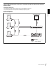
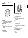
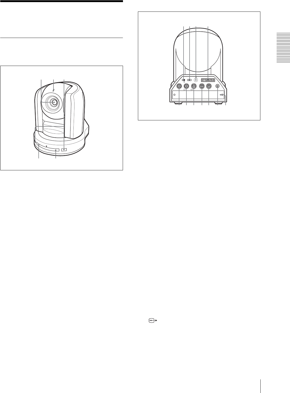
Camera
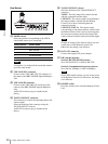
Front
A Lens
A wide conversion lens (not supplied) can be
attached.
B Tally lamp
Lights in red when a VISCA tally command is
received or the camera is selected by the RM-
BR300 Remote Control Unit (not supplied).
C Remote sensor
This is the sensor for the supplied Remote
Commander.
D POWER lamp
Lights when the camera is connected to an AC
outlet using the supplied AC power adaptor and AC
power cord.
Flaches in green when the camera receives an
operation command from the supplied Remote
Commander.
E STANDBY lamp
Lights when the camera is turned off using the
Remote Commander.
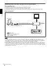
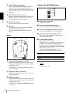
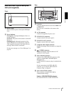
Rear
F 75-ohm termination switch
This switch is used when an external sync signal is
used. Set it to OFF when this camera is in the
middle of a daisy chain connection of multiple
cameras. Set it to ON when the camera is at the end
of a daisy chain connection.
G IR SELECT switch
Select the camera number when you operate
multiple cameras with the same Remote
Commander.
H Remote sensor
This is the sensor for the supplied Remote
Commander.
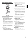
I VISCA RS-422 connector
Used for VISCA control.
A VISCA RS-422 connector plug is attached to the
camera at the factory.
For connection to the VSCA RS-422 connector, see
“Using the VISCA RS-422 Connector Plug” on
page 68.
J EXT SYNC IN connector
Accepts external video sync signals.
K T VIDEO connector
Supplies the images as composite signals.
L S VIDEO connector
Supplies the images as Y/C separate (S video)
signals.
P
O
W
E
R
S
T
A
N
D
B
Y
I
R
1
45
32
EXT SYNC IN
IR SELECT
75
1 2 3
OFF ON
IN VISCA RS-232C OUT
!
VISCA RS-422
1 2 3 4 5 6 7 8 9
DC IN
12V
R
VIDEO S VIDEO
0 q
a
q
s
q
d
q
f
q
g
678 9
q
h