


9 (GB)
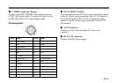
Pin No. Signal
A Power output
B GND
1 Trigger output
2 GND
3 GND
4 G/Y input
5 R/VBS input
6 GND
7 B/C input
8 GND
9—
10 —
11 —
Pin No. Signal
12 WE pulse input
13 Control
14 —
15 —
16 GND
17 —
18 HD input/output
19 GND
20 —
21 VD/SYNC input/output
22 —
23 —
24 —
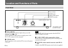
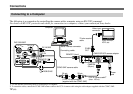
9 DC/AC SELECT switch
Set to the right position (AC IN) to operate the video camera
on the AC power supply connected to the AC IN connector.
Set to the left position (DC 15V IN) to operate the video
camera on the DC power supply connected to the DC 15V
IN connector.
q; AC IN connector
Connect to an AC outlet using the AC power cord
(supplied).
qa DC 15V IN connector
Connect to the DC power supply.
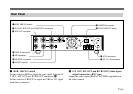
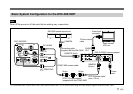
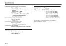
8 CAMERA connector (26-pin)
Connect to the DXC-390/390P video camera using the
CCMC-3MZ camera cable. To extend the cable, use the
CCMC-3MZ and CCZ-A series camera cables.
Pin assignment
A
B
1
6
23
12
18
24
11
17
22
7