


138
Chapter 7 Appendix
G
Gain
Indicator 22
Setting values for the GAIN
selector positions 103
GAIN SW page 77
GAIN switch 11
GAIN UP indicator 21
GAMMA page 81
GENLOCK IN connector 16
GENLOCK page 88
H
Hold indicator 23
HOURS METER page 91
I
I (interlace scan) mode 108
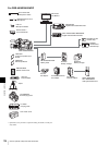
i.LINK
Checking the playback image
recorded on an external
VTR 42
Connecting 41
Making backup of recording
image 41
Settings required for an i.LINK
connection 41
Using the camcorder as a
feeder 42
i.LINK CTL setting 41
i.LINK DV OUT connector 8, 18, 41
ID number 23
Instant automatic iris adjustment
button 19
Interval rec 63
INTERVAL TIME 63
REC TIME 63
Settings before shooting 63
Shooting 63
Iris 55
Iris ring 19
Iris selector 19
Iris sensitivity 56
Iris sensitivity trimmer 56
Iris setting/auto iris override 22
K
KNEE page 81
L
LCD button 12
LCD monitor 11, 12
Display 23
Status display 98
LENS connector 9
LENS FILE page 79
LENS FILE 1 page 90
LENS FILE 2 page 90
LENS FILE 3 page 90
Lens locking lever 10
Lens mount 9
Lens mount cap 9
LIGHT connector 16
LIGHT switch 10, 20
Lithium battery
Attaching and Replacing 27
Service life 27
Warning indicator 24
Lithium battery compartment 14
LOW KEY SAT page 84
M
MACRO ring 20
MACRO selector 19
MAINTENANCE menu 84
MARKER 1 page 77
MARKER 2 page 77
“Memory Stick” 123
Displaying a file-related menu
page 117
Handling 109
Inserting 109
Protecting saved data 110
Removing 109
MEMORY STICK page 90
“Memory Stick” slot 18, 109
Menu
Adjustments and settings 103
Basic operations 93
DIAGNOSIS menu 91
Displaying 93
Ending 93
FILE menu 88
MAINTENANCE menu 84
OPERATION menu 75
Organization 66
PAINT menu 80
TOP menu 73
MENU knob 10
MENU switch 11
MIC IN connector 16
Model name and serial number
indicators 23
MONITOR knob 11
MONITOR OUT CHARACTER
switch 14
MONITOR OUT connector 16
MONITOR OUT page 75
MONITOR SELECT switch 14
Motorized zoom lever 19
Mounting the lens 28
MTX LINEAR page 83
MTX MULTI page 83
N
ND COMP page 88
Non drop-frame indicator 23
O
OFFSET WHT page 78
OPERATION menu 75
Operation/error message display
area 22
OPTION BOARD page 92
OUTPUT page 75
OUTPUT/DCC switch 11
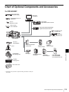
Overview 6
P
PAINT menu 80
PEAKING control 20
PLAY button and indicator 13
Playback
Indicator 23
On the color video monitor 65
Recording review 65
Power supply
Preparing 29
POWER switch 11
Pre-lighting function 63
PRESET WHT page 86
PRESET/REGEN/CLOCK switch 14
Product configurations 6
PsF (progressive scan) mode 108
R
REC button 9
REC TRIGGER switch 15
REC/SAVE switch 48
REC/TALLY indicators 21
Recording format
Indicator 22
Selecting 49
Recording shot data superimposed on
the color bars 101
Reference file 116
REFERENCE page 89
Remaining tape capacity 22
REMOTE connector 18
Remote control unit
Camcorder switch functions when
connected 37
Connecting 37
Paint adjustment when
connected 37
RM-B150/B750 37