


10
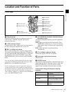
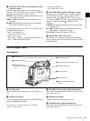
Location and Function of Parts
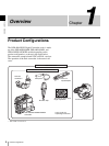
Chapter 1 Overview
* The range over which the subject is sharply in focus. Thus, “reducing the
depth of field” means that the range is reduced as well, and “increasing the
depth of field” means that it is increasing as well.
h ZEBRA button
Press to display a zebra pattern (diagonal stripes) in the
viewfinder screen.
The zebra pattern is factory set to indicate picture areas
where the video level is approximately 70%. However, on
the VF SETTING page of the OPERATION menu, you
can change the setting so that areas where the video level
is 100% and above also displayed at the same time.
For details, see “Setting the viewfinder” on page 100.
i ASSIGN 1/2 switches
You can assign the desired functions on the FUNCTION 1
page of the OPERATION menu.
For details, see “Assigning functions to ASSIGN
switches” on page 106.
j Lens locking lever
After inserting the lens in the lens mount, rotate the lens
mount ring with this lever to lock the lens in position.
k MENU knob
Changes the page selection or a setting within the menu.
For details about how to use the MENU knob, see “Basic
menu operations” on page 93.
l SHUTTER switch
Set to ON to use the electronic shutter. Flick to SEL to
switch the shutter speed or shutter mode setting within the
range previously set with the menu. When this switch is
operated, the new setting appears on the setting change/
adjustment progress message display area for about 3
seconds.
For details about the shutter speed and shutter mode
settings, see
“Setting the electronic shutter” on page 52.
m AUDIO LEVEL knob
Adjusts the channel 1 audio input level manually. You can
invalidate the setting of this knob in the F AUDIO VOL
item on the AUDIO page of the MAINTENANCE menu.
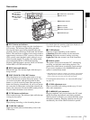
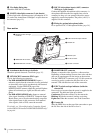
Right side view
Front section
a 5600K button
Press to lit the button and switch the standard color
temperature for shooting to 5600K. Use this button for
outdoor shooting in daytime or shooting under lighting
with higher temperature. While setting the wide-band
white balance, the button does not function.
b LIGHT switch
Determines how a video light connected to the LIGHT
connector
(page 16) is turned on and off.
AUTO: When the POWER switch of the video light is in
the on position, the video light is turned on
automatically while the camcorder is recording.
When using the interval recording mode, the video
light is automatically turned on immediately before
recording starts.
MAN: You can turn the video light on or off manually,
using its own switch.
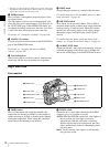
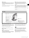
3 OUTPUT/DCC switch
1 5600K button
4 GAIN switch
6 MONITOR knob
7 ALARM knob
2 LIGHT switch
5 POWER switch
8 LCD monitor
9 MENU switch
0 WHITE BAL switch