


D
E
F
H
I
G
C
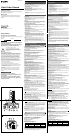
0: Whole screen/
Totalité de l’écran
1: Center (small)/
Centre (petit)
2: Lower left/
Bas gauche
3: Lower right/
Bas droite
4: Center (bottom)
Centre (bas)/
5: Upper left/
Haut gauche
6: Upper right/
Haut droite
7: Center (large)/
Centre (grand)
0
2
4
6
1
3
5
7
1
2
3
4
1
4
2
5
3
1
2
3
4
7
6
5
1
2
3
4
8
7
9
5
6
1
2
4
9
8
5
7
3
6
1
2
3
4
5
6
8
Installation
Suitable lenses
The lens must be either a C- or a CS-mount type of less than 1 kg. The
protrusion behind the mounting surface must be within the following limits:
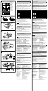
1 C-mount lens, 2 9 mm or less, 3 CS-mount lens, 4 4 mm or less
Changing the plug on an auto-iris lens cable
The camera is supplied with a plug to fit the LENS connector. To connect
an auto-iris lens, first replace the plug on the lens cable with the supplied
plug.
1 Detach the old plug from the lens cable.
2 Solder the lens cable to the pins of the supplied plug. (For cable pin
assignment, refer to the instruction manual for the lens.)
1 Cover
2 Lens cable
3 Rib (If the cable is thick, cut this off.)
4 Plug (unit accessory)
5 Pin 4 Video signal control Ground
DC control Ground
6 Pin 2 Video signal control Not used
DC control Control +
7 Pin 1 Video signal control Power supply (DC 9 V, 50 mA)
DC control Control –
8 Pin 3 Video signal control Video signal
DC control Drive +
Fitting the lens
1 Unscrew the lens mount cap.
2 Screw in the lens, and turn it until it is secured.
3 Insert the lens plug in the LENS connector.
When fitting a manual-iris lens, omit step 3.
4 Adjust the flangeback by turning the C/CS adjustment ring.
5 Tighten the locking screw.
Caution
When mounting the lens, loosen the securing nut on the side and turn the
flangeback adjustment to the “C” position. Mounting a C-mount lens with the
adjustment ring in the “CS” position may damage the optical filter. Keep the
lens mount cap on the camera when not attaching a lens.
Installing the camera
When mounting the camera on a tripod, attach the tripod adaptor to either
the top or bottom of the camera. Use a 1/4" UNC-20 screw to mount the
camera on a tripod.
Fitting the camera tripod adaptor
G
1 Loosen screws 1–4 that secure the tripod adaptor. Remove the
adaptor carefully, and do not pull at the screws.
2 Remove screws 5 and 6.
3 Attach the tripod adaptor on the opposite side, and insert screws 5
and 6 on the surface from which the adaptor was removed.
Connections
Using a DC 12 V power supply
Set the MODE switch (mode change switch) to B. When the connections
have been made, set the DC 12 V power supply switch to ON.
Notes
• To prevent short circuits, do not let the exposed ends of the mains lead
wires touch each other when connecting to the mains lead terminals.
• If you use the CMA-D2 camera adaptor (not supplied), you will need the
camera cable CCMC-200/200YC (not supplied). For further details, see
the cable manual.
Using an external synchronization signal H
1 DXC-190 (rear) 7
Synchronization signal (e.g., switcher)
2 VIDEO OUT connector 8 Power supply
3 75-ohm coaxial cable 9 DC 12 V switch (set to ON)
4 VIDEO INPUT connector 0 MODE switch (set to B)
5 VS IN connector qa +12 V
6
Synchronization output connector
qs GND (ground)
Using an internal synchronization signal H
To operate with an internal synchronization signal, no connection to the
synchronization signal source (5, 6 and 7 above) is necessary.
Using a YS-W170/W270 camera adaptor
(not supplied) (Power multiplex)
Set the MODE switch (mode change switch) to A. When the connections
have been made, set the YS-W170/W270 power supply switch to ON.
1 DXC-190 (rear) 7 VIDEO OUT connector
2 DC IN. VS IN/VIDEO OUT 8 VIDEO INPUT connector (monitor
connector input connector)
3 CAMERA IN connector 9 Portable monitor
4 MONITOR OUT connector 0 75-ohm coaxial cable
5 VIDEO INPUT connector qa MODE switch (set to A)
6 YS-W170/W270 camera
adaptor (rear)*
* The figure shows the YS-W170 camera adaptor.
Phase Adjustment
When using more than one camera, adjust the phase according to the
following procedure.
Horizontal phase (VS/VBS lock mode)
The picture may shift horizontally when using an extended cable. Use the
PHASE volume to adjust the horizontal phase.
CCD Characteristics
The following conditions may be observed when using a CCD camera. They
are not due to any fault within the camera.
Vertical smear
This phenomenon occurs when viewing a very bright object.
Patterned noise
This is a fixed pattern that may appear over the entire monitor screen when
the camera is operated at high temperatures.
Jagged picture
When viewing stripes, straight lines, or similar patterns, the image on the
screen may appear jagged.
Specifications
Image device 1/2type interline transfer CCD
Effective picture elements
768 (horizontal) × 494 (vertical)
Lens mount C-mount/CS-mount adjustable
Signal system NTSC color system
Synchronization system internal/external (switched automatically)
External synchronization signal VBS/VS (sync level: 0.3–5.0 Vp-p, 75 ohm)
Horizontal resolution 470 TV lines
Minimum illumination 0.8 lux, F 1.2
(
with AGC set to ON in TURBO
mode)
Video output 1 Vp-p, 75 ohm, negative sync
Video S/N
50 dB or more (with AGC set to OFF, Weight ON)
Electronic shutter 8 levels
1/60, 1/100, 1/250, 1/500, 1/1000, 1/2000,
1/4000, 1/10000
White balance AWB/5600K/ATW/ATWpro (switchable)
Automatic gain control (AGC) ON/OFF switchable
Power requirements
DC 12 V ±10%
(DC 12 V for power source)
DC 24 V ±5 V (when YS- W170/W270 is in use)
Power consumption 4.5 W (DC 12 V for power source)
5.5 W (when YS-W170/W270 is in use)
Operating temperature –10 °C to +50 °C (14 °F to 122 °F)
Operating humidity 20 to 80%
Storage temperature –40 °C to +60 °C (–40 °F to 140 °F)
Storage humidity 20 to 95%
Shock resistance 70 G
Mass 600 g (1 lb 5 oz)
Dimensions 64 × 57 × 137 (w/h/d) mm
(2
5
/8 × 2
1
/4 × 5
1
/2 inches)
Supplied accessories 4-pin plug for auto-iris lens (1)
Lens mount cap (1)
Operating Instructions (1)
Design and specifications are subject to change without notice.
F
D
E
Installation
Objectifs compatibles
L’objectif doit être à monture C ou CS et peser moins de 1 kg. La saillie de la partie
arrière de l’objectif ne peut dépasser les limites suivantes : 1 Objectif à monture C,
2 9 mm ou moins, 3 Objectif à monture CS, 4 4 mm ou moins
Remplacement de la fiche d’un câble d’objectif à
diaphragme automatique
La caméra est fournie avec une fiche pour le connecteur LENS. Pour raccorder un
objectif à diaphragme automatique, remplacez d’abord la fiche du câble d’objectif par
la fiche fournie.
1 Déposez la fiche d’origine du câble d’objectif.
2 Soudez le câble d’objectif aux broches de la fiche fournie. (Pour l’attribution des
broches, consultez le mode d’emploi de l’objectif.)
1 Bouchon
2 Câble d’objectif
3 Nervure (découpez-la si le cordon est de forte section)
4 Fiche (accessoire)
5 Broche 4 Command du signal vidéo Masse
Commande CC Masse
6 Broche 2 Command du signal vidéo Non utilisé
Commande CC COMM +
7 Broche 1 Command du signal vidéo Alimentation (9 V CC, 50 mA)
Commande CC COMM –
8 Broche 3 Command du signal vidéo Signal vidéo
Commande CC ENTR +
Montage de l’objectif
1 Dévissez le bouchon d’objectif.
2 Vissez l’objectif et tournez jusqu’à ce qu’il se verrouille.
3 Branchez la fiche d’objectif sur le connecteur LENS.
Si vous utilisez un objectif à diaphragme manuel, passez l’étape 3.
4 Réglez la distance focale en tournant la bague de réglage C/CS.
5 Serrez la vis de blocage.
Attention
Lorsque vous montez l’objectif, desserrez l’écrou de verrouillage situé sur le côté et
tournez la bague de réglage de la distance focale sur la position “C”. L’installation d’un
objectif à monture C avec la bague de réglage sur la position “CS” risque
d’endommager le filtre optique. Laissez le bouchon d’objectif sur la caméra lorsque
vous n’y montez pas d’objectif.
Installation de la caméra
Lorsque vous montez la caméra sur un trépied, attachez l’adaptateur de trépied en
haut ou en bas de la caméra. Servez-vous d’une vis 1/4" UNC-20 pour monter la
caméra sur un trépied.
Fixation de l’adaptateur de trépied G
1 Desserrez les vis 1 à 4 qui fixent l’adaptateur de trépied. Retirez l’adaptateur avec
précaution, en évitant de tirer sur les vis.
2 Retirez les vis 5 et 6.
3 Fixez l’adaptateur de trépied du côté opposé, et introduisez les vis 5 et 6 sur le
côté où le support a été enlevé.
Raccordements
Avec une alimentation 12 V CC
Réglez le commutateur MODE (commutateur changement de mode) sur B. Quand les
raccordements sont faits, réglez l’interrupteur d’alimentation DC 12 V sur ON.
Remarques
• Pour éviter un court-circuit, veillez à ce que les extrémités exposées des fils du câble
d’alimentation ne se touchent pas lorsque vous raccordez les bornes du câble
d’alimentation.
• Si vous utilisez l’adaptateur de caméra CMA-D2 (non fourni), vous aurez besoin du
câble de caméra CCMC-200/200YC (non fourni). Pour obtenir davantage de détails,
consultez le manuel traitant du câble.
Utilisation du signal de synchronisation externe
H
1 DXC-190 (à l’arrière) 7 Signal de synchronisation
2 Connecteur VIDEO OUT (par ex., sélecteur)
3 Câble coaxial de 75 ohms 8 Alimentation électrique
4 Connecteur VIDEO INPUT 9 Interrupteur d’alimentation
5 Connecteur VS IN DC 12 V (réglé sur ON)
6 Connecteur de sortie de 0 Commutateur MODE (réglé sur B)
synchronisation qa +12 V
qs GND (masse)
Utilisation du signal de synchronisation interne
H
Pour utiliser l’appareil avec un signal de synchronisation interne; aucune connexion à
la source de signal de synchronisation (5, 6 et 7 ci-dessus) n’est requise.
Avec un adaptateur de caméra YS-W170/W270
(non fourni) (Power multiplex)
Réglez le commutateur MODE (commutateur changement de mode) sur A. Quand les
raccordements sont faits, réglez l’interrupteur d’alimentation YS-W170/W270 sur ON.
1 DXC-190 (à l’arriére) 7 Connecteur VIDEO OUT
2
Connecteur DC IN. VS IN/VIDEO OUT
8 Connecteur VIDEO INPUT
3 Connecteur CAMERA IN
(connecteur d’entrée du moniteur)
4 Connecteur MONITOR OUT 9 Moniteur portable
5 Connecteur VIDEO INPUT 0 Câble coaxial de 75 ohms
6 Adaptateur de caméra qa Commutateur MODE (réglé sur A)
YS-W170/W270 (à l’arriére)*
* La figure représente l’adaptateur de caméra YS-W170.
Réglage de phase
Si vous utilisez plus d'une caméra, réglez la phase conformément à la procédure
suivante.
Phase horizontale (mode VS/VBS LOCK)
L’image peut être décalée horizontalement lorsque vous utilisez une allonge de câble.
Utilisez le volume PHASE pour régler la phase horizontale.
Caractéristiques du capteur CCD
Il se peut que vous observiez les phénomènes suivants lors de l’utilisation d’une
caméra CCD. Ils ne sont cependant pas synonymes d’une défaillance de la caméra.
Maculage vertical
Ce phénomène se manifeste lors de la visualisation d’objets très lumineux.
Parasites périodiques
Il s’agit d’un motif fixe qui peut apparaître sur toute la surface de l’écran du moniteur
lorsque la caméra est utilisée sous des températures élevées.
Image ondulatoire
Lors de la visualisation de rayures, de lignes droites ou de motifs similaires, l’image à
l’écran peut sembler irrégulière.
Spécifications
Système d’image CCD à transfert et interligne de type 1/2
Eléments d’image effectifs 768 (horizontal.) × 494 (vertical.)
Monture d’objectif Monture C/monture CS commutable
Système de signal Système couleur NTSC
Système de synchronisation Interne/externe (commutation automatique)
Signal de synchronisation externe VBS/VS (niveau synchro: 0,3-5,0 Vp-p, 75
ohms)
Résolution horizontale 470 lignes
Eclairement minimum 0,8 lux, F 1,2 (AGC réglé sur ON en mode
TURBO)
Sortie vidéo 1 Vp-p, 75 ohms, sync négative
Rapport signal/bruit vidéo 50 dB ou plus (AGC réglé sur OFF, Weight
ON)
Obturateur électronique 8 niveaux
1/60e, 1/100e, 1/250e, 1/500e, 1/1000e,
1/2000e, 1/4000e, 1/10000e
Balance des blancs AWB/5600K/ATW/ATWpro (commutable)
Réglage automatique du gain (AGC) ON/OFF (commutable)
Puissance de raccordement 12 V CC ±10% (source d’alimentation 12 V
CC)
24 V CC ±5 V (si YS-W170/W270 est utilisé)
Consommation électrique 4,5 W (source d’alimentation 12 V CC)
5,5 W (si YS-W170/W270 est utilisé)
Température d’utilisation –10 °C à +50 °C (14 °F à 122 °F)
Humidité d’utilisation 20 à 80%
Température de stockage –40 °C à +60 °C (–40 °F à 140 °F)
Humidité de stockage 20 à 95%
Résistance aux chocs 70 G
Masse 600 g (1 lb 5 oz)
Dimensions
64 × 57 × 137 (l/h/p) mm
(2
5
/8 × 2
1
/4 × 5
1
/2 pouces)
Accesoires fournis Fiche à 4 broches pour l’objectif à diaphragme
automatique (1)
Bouchon d’objectif (1)
Mode d’emploi (1)
La conception et les spécifications sont sujettes à modifications sans préavis.
D
E
F
I
I
qa
0
qa
qs
0
8
7