


Formats and Limitations of Outputs
117
Appendixes
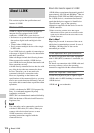
Phenomena specific to CMOS image
sensors
The following phenomena that may appear in
images are specific to CMOS (Complementary
Metal Oxide Semiconductor) image sensors.
They do not indicate malfunctions.
White flecks
Although the CMOS image sensors are produced
with high-precision technologies, fine white
flecks may be generated on the screen in rare
cases, caused by cosmic rays, etc.
This is related to the principle of CMOS image
sensors and is not a malfunction.
The white flecks especially tend to be seen in the
following cases:
• when operating at a high environmental
temperature
• when you have raised the master gain
(sensitivity)
• when operating in Slow-Shutter mode
Aliasing
When fine patterns, stripes, or lines are shot, they
may appear jagged or flicker.
Flicker
If recording is made under lighting produced by
discharge tubes, such as fluorescent, sodium, or
mercury-vapor lamps, the screen may flicker,
colors may vary, or horizontal stripes may appear
distorted. In such cases, turn the Flicker-
Reduction function on (see page 51).
In some cases, such phenomena may not be
improved with the Flicker-Reduction function.
It is recommend to set the electronic shutter speed
to
1
/
100
sec. in 50-Hz areas and to
1
/
60
in 60-Hz
areas.
Focal plane
Owing to the characteristics of the pickup
elements (CMOS sensors) for reading video
signals, subjects that quickly move across the
screen may appear slightly skewed.
The format of output signals from the
COMPONENT OUT connector and the SDI
OUT connector varies according to the recording/
playback video formats and the kind of the output
signal (the setting of “YPbPr/SDI Out Select” of
the VIDEO SET menu).
Output formats in E-E mode
1)
/recording
mode (Camera mode)
Analog component signals from the
COMPONENT OUT connector are output in the
format shown below according to the “Video
Format” setting of the OTHERS menu and the
“YPbPr/SDI Out Select” setting (HD or SD) of
the VIDEO SET menu.
The SDI OUT connector outputs serial digital
signals of the same format as that of the analog
component signals fed from the COMPONENT
OUT connector.
1)E-E mode: Recording standby status
Note
No signal is output from the A/V OUT connector
when “YPbPr/SDI Out Select” of the VIDEO
SET menu is set to “HD” or “SD.”
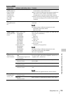
Formats and Limitations
of Outputs
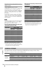
Video Formats and Output
Formats
Video
format
Output format
YPbPr Out
Select: HD
YPbPr Out
Select: SD
1080/59.94i 1080/59.94i 480/59.94i
1080/29.97P 1080/29.97PsF 480/59.94i
1080/23.98P 1080/59.94i 480/59.94i
720/59.94P 720/59.94P 480/59.94i
720/29.97P 720/59.94P 480/59.94i
720/23.98P 720/59.94P 480/59.94i
1080/50i 1080/50i 576/50i
1080/25P 1080/25PsF 576/50i
720/50P 720/50P 576/50i
720/25P 720/50P 576/50i