


Installation
Caution
Request for an expert to install it to the ceiling.
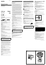
Attaching the fall-prevention wire rope
When you install the camera on a ceiling or a high position, be sure to attach the
supplied fall-prevention wire rope to prevent the camera from falling.
Attach the fall-prevention wire rope to the screw hole on the rear of the camera,
as in the illustration.
Note
Take care not to short-circuit the power terminal or the cable with the wire rope
when you attach it.
1 Secure the wire rope to the junction box on the ceiling.
Use a screw to match the screw hole of your junction box (not supplied).
2 Secure the wire rope to the wire rope mounting screw hole on the rear of
the camera using the supplied shoulder screw.
Caution
Use the supplied screws for installation. If not, the wire rope may not function
properly.
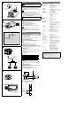
Adjusting the Camera Coverage and Focus
1 Loosen the zoom ring locking screw to adjust the camera shooting
coverage.
2 Tighten the locking screw to fix the zoom.
3 Loosen the focus ring locking screw to adjust the focus.
4 Tighten the locking screw to fix the focus.
5 Press the Easy Focus button on the rear to automatically adjust the
focus.
Note
You may not achieve satisfactory focus with the Easy Focus button due to the
shooting environment.
In this condition, press and hold Easy Focus button for more than 4 seconds to
return to the default flange back position. Then, adjust the focus following
step 3 and 4.
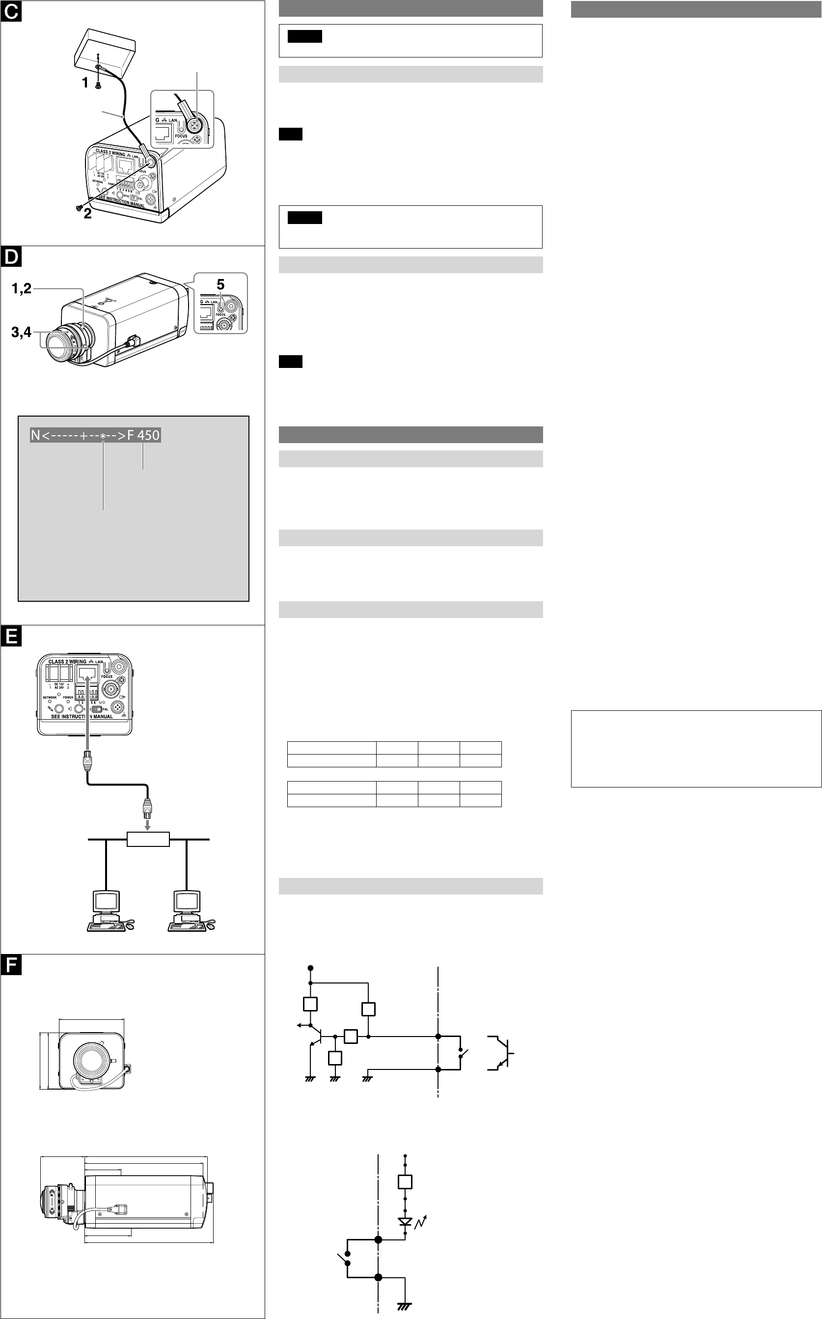
Connection
Connecting to the Network
Connect the LAN cable of the camera to a router or hub in the network using the
network cable (straight, not supplied).
To connect to a computer
Connect the LAN cable of the camera to the network connector of a computer
using the network cable (cross, not supplied).
Connecting the Power Source
There are three ways to supply power to this camera, as follows.
12 V DC
24 V AC
Power supply equipment pursuant to IEEE802.3af (PoE* system)
*PoE means Power over Ethernet.
Connecting to 12 V DC or 24 V AC source
Connect the power input cable of the camera to a 12 V DC or 24 V AC source.
Use a 12 V DC or 24 V AC source isolated from 100 to 240 V AC. The acceptable
voltage ranges for each are as follows.
12 V DC: 10.8 V to 13.2 V
24 V AC: 21.6 V to 26.4 V
- In the USA, The product shall be powered by a UL Listed Class 2 Power
Supply Only.
- In Canada, The product shall be powered by a CSA certified Class 2 Power
Supply Only.
Use UL cable (VW-1 style 10368) for these connections.
recommended cable
DC12V:
CABLE(AWG) #24 #22 #20
Max. length(m) 8 14 20
AC24V:
CABLE(AWG) #24 #22 #20
Max. length(m) 33 57 83
Connecting to the power supply equipment pursuant to
IEEE802.3af
The power supply equipment pursuant to IEEE802.3af supplies the power
through the LAN cable. For details, refer to the Instruction Manual of the
equipment.
Connecting the I/O Cable
Connect the wires of the I/O cable as follows:
Wiring diagram for sensor input
Mechanical switch/open collector output device
Camera inside Outside
or
GND
Mechanical
switch
Open collector
output device
3.3 V
2.2 k
Sensor input −
(GND)
10 k
GND GND
10 k
10 k
Sensor input +
Wiring diagram for alarm output
R
Camera inside Outside
5 V
Alarm Output +
GND
Magnet relay
AC 24 V
DC 24 V
1 A or less
Circuit example
Alarm Output −
Specifications
Compression
Video compression format JPEG/MPEG4/H.264
Audio compression format G.711/G.726 (40, 32, 24, 16 kbps)
Maximum frame rate JPEG/MPEG4/H.264: 30fps (1280 × 720)
JPEG: 30 fps (1280 × 1024)
MPEG4: 25 fps (1280 × 1024)
H.264: 20 fps (1280 × 1024)
Camera
Signal system NTSC color system/PAL color system (switchable)
Image device 1/3type CMOS (Exmor)
Effective picture elements: Approx. 1,390,000
Synchronization Internal synchronization
Horizontal resolution 600 TV lines (analog video)
Video S/N More than 50 dB (AGC 0 dB)
Minimum illumination
F1.2/View-DR Off/VE off/AGC High/XDNR
Middle/
50% Video Level
Color 0.20 lx
Black & White 0.10 lx
Lens
Focal length 2.8 mm to 8 mm
Maximum relative aperture F1.2
View angle Vertical: 76.2° ~ 27.2° (1280 × 1024)
Horizontal: 96.5° ~ 33.9°
Minimum object distance 300 mm
Interface
LAN port 10BASE-T/100BASE-TX, auto negotiation (RJ-45)
I/O port Sensor input : × 1, make contact, break contact
Alarm output : × 2, 24 V AC/DC, 1 A
(mechanical relay outputs electrically
isolated from the camera)
CF card slot CF Type I/II
Video output VIDEO OUT: BNC, 1.0 Vp-p, 75 ohms, unbalanced,
sync negative
Microphone input* Minijack (monaural)
Plug-in-power supported (rated voltage: 2.5 V
DC)
Recommended load impedance: 2.2 k
Line input* Minijack (monaural)
* The microphone input and the line input are switchable with operating menu.
Line output Minijack (monaural), Maximum output level: 1
Vrms
Others
Power supply 12 V DC ± 10%
24 V AC ± 10%, 50/60 Hz
IEEE802.3af compliant (PoE system)
Power consumption 9.0 W max.
Operating temperature Working temperature: 0°C~50°C (32°F to 122°F)
Start temperature: –10°C~+50°C (14°F to 122°F)
Storage temperature –20°C to 60°C (–4°F to 140°F)
Operating humidity 20% to 80%
Storage humidity 20% to 95%
Dimensions (w/h/d)
72 × 63 × 197 mm (2 / × 2 / × 7 / inches) with
lens not including the projecting parts
72 × 63 × 145 mm (2
/ × 2 / × 5 / inches) not
including the projecting parts
Mass Approx. 600 g (1 lb 5 oz) with lens
Supplied accessories CD-ROM (Users Guides, and supplied programs)
(1)
Fall-prevention wire rope (1)
Shoulder screw M4 (1)
Installation Manual (this document) (1)
Optional accessories Wireless card SNCA-CFW5*
Wireless LAN antenna SNCA-AN1*
* SNCA-CFW5, SNCA-AN1 may not be
purchasable in some regions. For details,
contact your Sony service representative.
Design and specifications are subject to change without notice.
Recommendation of Periodic Inspections
In case using this device over an extended period of time, please have it
inspected periodically for safe use.
It may appear flawless, but the components may have deteriorated over
time, which may cause a malfunction or accident.
For details, please consult the store of purchase or an authorized Sony
dealer.
Shoulder screw
(supplied)
Fall-prevention wire
rope (supplied)
When Easy Focus button is pressed
Network cable
(straight, not
supplied)
10BASE-T/
100BASE-TX
Router or hub
72 (2 /)
63 (2 /)
62 (2 /)
Front
Unit: mm (inches)
Side
145 (5 /)
140 (5 /)
52 (2 /)
43 (1 /)
55 (2 /)
152 (6)
* mark indicates the
approximate focus position.
The number indicates
the focus position.