


1, 2
3
4
5
SNC-DH140/DH240 SNC-DH140T/DH240T
Dome casing
wrench
cable cover
Rating label
When ZOOM/FOCUS switch slides to N/F
When ZOOM/FOCUS switch slides to W/T
SNC-DH140/DH240 SNC-DH140T/DH240T
Ceiling
Network cable
(straight, not
supplied)
10BASE-T/
100BASE-TX
Router or hub
LAN cable
Ceiling
Power input cable
SNC-DH140/DH240 SNC-DH140T/DH240T
Unit: mm (inches)
Ø140 (5
5
/
8
)
118 (4
3
/
4
)
Ø140 (5
5
/
8
)
119 (4
3
/
4
)
Preparations
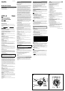
Connecting the Cables to the Camera
Before installation, connect the supplied cables to the camera as required for
your usage and wire them.
1 Remove the screw on the bottom of the camera unit to detach the cable
cover.
2 Pass the cables through the hole on the bottom of the camera unit.
3 Connect the cables to the connectors on the camera unit.
I/O cable: to EXT CTRL connector
BNC cable: to VIDEO OUT connector
Audio cable: to AUDIO connector
4 Wire the cables along the cable guides on the camera unit. Position the
cables under the cable clamps.
Note
To prevent the cables from being trapped by the dome casing, be sure to
wire them using the cable guides and clamps.
5 Pull the cables gently from the bottom of the camera unit to take in the
slack, and fix the cable cover with the screw.
To install the camera for indoor wiring, push the indoor wiring cover
outwards and then remove it and pass the cables through it.
Installation
WARNING
If you attach the camera in the height such as the wall or the ceiling, etc.,
entrust the installation to an experienced contractor or installer.
If you install the camera on the ceiling, ensure that the ceiling is strong
enough to withstand the weight of the camera plus the bracket and then
install the camera securely. If the ceiling is not strong enough, the camera
may fall and cause serious injury.
To prevent the camera from falling, make sure to attach the supplied wire
rope.
If you attach the camera to the ceiling, check periodically, at least once a
year, to ensure that the connection has not loosened. If conditions warrant,
make this periodic check more frequently.
Deciding the Installation Location of the Camera
After deciding the direction in which the camera will shoot, make the required
hole (ø 50 mm (2 inches)) for the connecting cables using the supplied
template. Then decide the two or four mounting hole positions to install the
bracket.
Mounting screws
The supplied bracket is provided with ø 4.5 mm (
3
/
16
inch) mounting holes.
Install the bracket on a ceiling or wall with screws through two or four mounting
holes: two 83.5 mm (3
9
/
32
inches)-pitched holes or four 85.7 mm
(3
3
/
8
inches)-pitched holes. The required mounting screws differ depending on
the installation location and its material. (Mounting screws are not supplied.)
Steel wall or ceiling: Use M4 bolts and nuts.
Wooden wall or ceiling: Use M4 tapping screws. The panel thickness must be
15 mm (
5
/
8
inch) or more.
Concrete wall: Use anchors, bolts and plugs suitable for concrete walls.
Junction box: Use screws to match the holes on the junction box.
WARNING
The required mounting screws differ depending on the installation location and
its material. If you do not secure the camera with the appropriate mounting
screws, the camera may fall off.
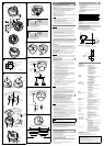
Installing the Camera
1 Remove the dome casing.
SNC-DH140/DH240
Pull out the screw cover and loosen the screw with a screwdriver.
Turn the dome casing to the curved mark position on the camera unit,
and remove the dome casing from the camera unit. When the screw
catches on the screw hole, pull up the screw.
SNC-DH140T/DH240T
Loosen the screw with the wrench (supplied).
Turn the dome casing to the curved mark position on the camera unit,
and remove the dome casing from the camera unit. When the screw
catches on the screw hole, pull up the screw.
2 Install the supplied bracket on the ceiling or wall.
Refer to “Mounting screws” for screws to be used.
3 Fix the supplied wire rope to the camera unit and the ceiling or wall.
Fix the wire rope with the supplied shoulder screw to the hole for the
wire rope on the bottom of the camera unit.
Pass the wire rope between the wire rope guides.
Fix the wire rope to the ceiling or wall.
4 Attach the camera unit to the bracket.
Insert the supplied two camera unit mounting screws into the two
mounting holes of the camera.
The screws have a fall-prevention mechanism. The screws inserted into
the screw holes of the camera unit do not fall even if you turn the camera
unit upside down.
Align the notch on the camera with the f mark on the bracket.
Turn the camera unit in the direction of the arrow.
Tighten the camera unit mounting screws.
Notes
Use the supplied screws for installation. otherwise, you may not install the
camera unit properly, even a falling may occur.
If you cannot use screws on a ceiling or wall, or if you want to make the
camera less conspicuous, use the YT-ICB45/YT-ICB140 in-ceiling bracket
(optional) with which you can mount the camera on the ceiling.
For this model, install the camera to the position on the side brackets of
YT-ICB45/YT-ICB140. Refer to the Installation Instructions of YT-ICB45/
YT-ICB140 for detail information.
Adjusting the Camera Direction and Coverage
1 Loosen the camera head fixing screw.
2 Adjust the camera to turn the lens in the desired direction.
3 Tighten the camera head fixing screw to fix the camera.
4 Slide the ZOOM/FOCUS switch to W/T to adjust the zoom.
The zoom indicator is displayed on the monitor.
5 Press the Easy Focus button to automatically adjust the focus.
6 Repeat steps 1 to 5 until the coverage and the focus are determined.
Notes
When you adjust the camera head angle without loosening camera head
fixing screw, an internal part may be damaged.
When the lens is not put in the slit of the camera head holder, the moving
range of the camera head is limited.
If the camera head is too heavy to be adjusted, loosen the camera head fixing
screw until it moves freely.
When adjusting the angle, be sure that the TOP mark on the camera head
section faces the ceiling. If the camera is installed with the TOP mark facing
the floor, the image appears upside down.
If you cannot achieve satisfactory focus with the Easy Focus button due to the
shooting environment, slide the ZOOM/FOCUS switch level to N/F to focus
manually. The focus indicator is displayed on the monitor.
Poor focus may also be caused by the dome case assembly. Readjust the
focus using the system menu.
For details, refer to the User Guide of the equipment.
Note
Do not turn the lens more than 360 degrees, as this may damage the wiring inside,
which may cause failure on video output.
Attaching the Dome Casing
1 Align the carved mark on the dome casing with that on the camera unit,
and turn the dome casing in the direction of the arrow.
2 Secure the screw. Only the SNC-DH140/240 cover should be attached.
3 Remove the protecting film on the dome cover.
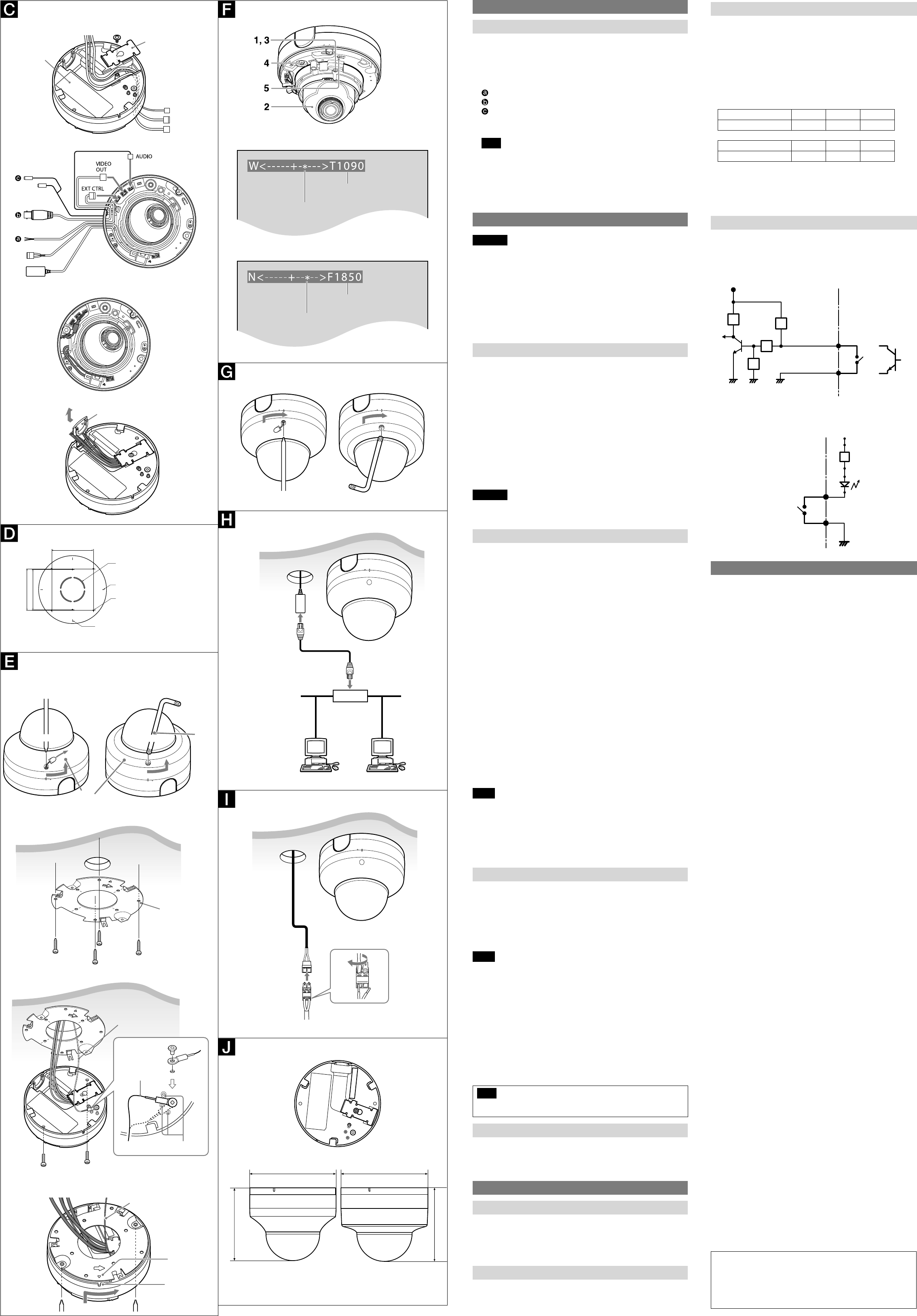
Connection
Connecting to the Network
Connect the LAN cable of the camera to a router or hub in the network using
the network cable (straight, not supplied).
To connect to a computer
Connect the LAN cable of the camera to the network connector of a computer
using the network cable (cross, not supplied).
Connecting the Power Source
There are three ways to supply the power source to this camera, as follows.
12 V DC
24 V AC
Power supply equipment pursuant to IEEE802.3af (PoE* system)
*PoE means Power over Ethernet.
Connecting to 12 V DC or 24 V AC source
Connect the power input cable of the camera to a 12 V DC or 24 V AC source.
Use a 12 V DC or 24 V AC source isolated from 100 to 240 V AC. Each usable
voltage ranges are as follows.
12 V DC: 10.8 V to 13.2 V
24 V AC: 21.6 V to 26.4 V
- In the USA, The product shall be powered by a UL Listed Class 2 Power
Supply Only.
- In Canada, The product shall be powered by a CSA certified Class 2
Power Supply Only
Use UL cable (VW-1 style 10368) for these connections.
recommended cable
DC12 V:
CABLE(AWG) #24 #22 #20
Max. length(m) 9 15 23
AC24 V:
CABLE(AWG) #24 #22 #20
Max. length(m) 37 63 92
Connecting to the power supply equipment pursuant to
IEEE802.3af
The power supply equipment pursuant to IEEE802.3af supplies the power
through the LAN cable. For details, refer to the Instruction Manual of the
equipment.
Connecting the I/O Cable
Connect the wires of the I/O cable as follows:
Wiring diagram for sensor input
Mechanical switch/open collector output device
Camera inside
3.3 V
2.2 K
Ω
Sensor input +
GND
Mechanical switch
Open collector
output device
Outside
or
GNDGND
10 K
Ω
10 K
Ω
10 K
Ω
(GND)
Sensor input −
Wiring diagram for alarm output
R
Camera inside
Alarm Output +
Magnet relay –
24 V AC
24 V DC,
1 A or less
Alarm Output –
Outside
5 V
Circuit example
GND
Specifications
Compression
Video compression format JPEG/MPEG4/H.264
Audio compression format G.711/G.726 (40, 32, 24, 16 kbps)
Maximum frame rate SNC-DH140/DH140T
JPEG/MPEG4/H.264: 30 fps (1280 × 720)
JPEG: 30 fps (1280 × 1024)
MPEG4: 25 fps (1280 × 1024)
H.264: 20 fps (1280 × 1024)
SNC-DH240/DH240T
JPEG: 15 fps (1920 × 1080) /
10 fps (1920 × 1440)
MPEG4: 25 fps (1920 × 1080) /
15 fps (1920 × 1440)
H.264: 30 fps (1920 × 1080) /
20 fps (1920 × 1440)
Camera
Signal system NTSC color system/PAL color system (switchable)
Image device SNC-DH140/DH140T
1/3type CMOS (Exmor)
Effective picture elements:
Approx. 1,390,000
SNC-DH240/DH240T
1/2.8type CMOS (Exmor)
Effective picture elements:
Approx. 3,270,000
Synchronization Internal synchronization
Horizontal resolution 600 TV lines (analog video)
Video S/N More than 50 dB (AGC 0 dB)
Minimum illumination SNC-DH140/DH140T
F1.2/View-DR Off/VE Off/AGC High/XDNR
Middle/50 IRE (IP)
Color 0.20 lx
Black & White 0.10 lx
SNC-DH240/DH240T
F1.2/View-DR Off/VE Off/AGC High/XDNR
Middle/50 IRE (IP)
Color 0.55 lx
Black & White 0.30 lx
Lens
Focal length 3.1 mm to 8.9 mm
Maximum relative aperture F1.2 ~ F2.1
View angle SNC-DH140/DH140T
Vertical: 67.4° to 25.0° (1280 × 1024)
Horizontal: 85.4° to 31.2°
SNC-DH240/DH240T
Vertical: 65.2° to 24.2° (1920 × 1440)
Horizontal: 88.5° to 32.3°
Minimum object distance 300 mm
Interface
LAN port 10BASE-T/100BASE-TX, auto negotiation (RJ-45)
I/O port Sensor input: × 1, make contact, break contact
Alarm output: × 2, 24 V AC/DC, 1 A
(mechanical relay outputs electrically
isolated from the camera)
Video output VIDEO OUT: BNC, 1.0 Vp-p, 75 ohms, unbalanced,
sync negative
Microphone input* Minijack (monaural)
Plug-in-power supported (rated voltage: 2.5 V
DC)
Recommended load impedance: 2.2 kΩ
Line input* Minijack (monaural)
* The microphone input and the line input are switchable with operating menu.
Line output Minijack (monaural), Maximum output level:
1 Vrms
Others
Power supply 12 V DC ± 10%
24 V AC ± 10%, 50/60 Hz
IEEE802.3af compliant (PoE system)
Power consumption SNC-DH140/DH140T: 8.0 W max.
SNC-DH240/DH240T: 10.2 W max.
Operating temperature Start temperature: 0°C ~ 50°C (32°F to 122°F)
Working temperature: −10°C ~ +50°C (14°F to
122°F)
Storage temperature –20°C to +60°C (–4°F to +140°F)
Operating humidity 20% to 80%
Storage humidity 20% to 95%
Dimensions (diameter/height)
SNC-DH140/DH240:
140 mm × 118 mm (5
5
/
8
inches × 4
3
/
4
inches)
SNC-DH140T/DH240T:
140 mm × 119 mm (5
5
/
8
inches × 4
3
/
4
inches)
Mass SNC-DH140/DH240:
Approx. 750 g (1 lb 10 oz), not including the
cables and bracket
SNC-DH140T/DH240T:
Approx. 980 g (2 lb 3 oz), not including the
cables and bracket
Supplied accessories CD-ROM (User’s Guides, and supplied
programs) (1), Bracket (1), Template (1), Wire
rope (1), Camera unit mounting screws (2),
Shoulder screw M4 (1), Wrench (SNC-DH140T/
DH240T) (1), Audio cable (1), I/O cable (1), LAN
cable (1), BNC cable (1), Power input cable (1),
Installation Manual (this document) (1 set)
Optional accessory
In-ceiling bracket YT-ICB45*, YT-ICB140*
* Using the fixture position on the bracket.
Design and specifications are subject to change without notice.
Recommendation of Periodic Inspections
In case using this device over an extended period of time, please have it
inspected periodically for safe use.
It may appear flawless, but the components may have deteriorated over
time, which may cause a malfunction or accident.
For details, please consult the store of purchase or an authorized Sony
dealer.
indoor wiring cover
Bracket
(supplied)
Ceiling
notch
mark
Wire rope
Ceiling
Wire rope (supplied)
Shoulder
screw
(supplied)
Wire rope
Camera unit mounting
screw (supplied) (2)
Guide
* mark indicates the
approximate zoom position.
The number indicates
the zoom position.
* mark indicates the
approximate focus position.
The number indicates
the focus position.
Unit: mm (inches)
85.7 (3
3
/
8
)
83.5 (2
9
/
32
)
Hole for connecting cables
ø50
Horizontal mark
Hole for installing the
bracket
Vertical mark
85.7 (3
3
/
8
)
2
3, 4
1