


Installation
Notes
Do not grasp the camera head when carrying the camera.
Do not turn the camera head manually. Doing so will result in the camera
malfunctioning.
Installing the Camera on the Ceiling
You can view the image of this camera in the normal direction when the camera
is installed on the ceiling.
Using the supplied ceiling brackets, wire rope and screws, you can utilize existing
junction boxes, etc., to attach the camera to the ceiling.
When you install the camera, always install it on a level ceiling. If you have to
install it on a sloping or uneven ceiling, make sure that the place where you
install it is within ±5 degrees of the horizontal in order to ensure the pan/tilt
mechanism functions properly.
Warning
If you attach the camera in the height such as the wall or the ceiling, etc.,
entrust the installation to an experienced contractor or installer.
If you install the camera on the ceiling, ensure that the ceiling is strong
enough to withstand the weight of the camera plus the ceiling brackets
and then install the camera securely. If the ceiling is not strong enough,
the camera may fall and cause serious injury.
To prevent the camera from falling, make sure to attach the supplied
wire rope.
If you attach the camera to the ceiling, check periodically, at least once
a year, to ensure that the connection has not loosened. If conditions
warrant, make this periodic check more frequently.
Before installation
After deciding the direction in which the camera will shoot, make the required
holes for the junction box, and connecting cables.
Note
The connecting cables cannot be passed through the upper ceiling bracket. A
hole for the wiring is required in the ceiling at the back of the camera where it is
attached to the ceiling.
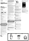
Installation
1 Attach the fall-prevention wire rope to the junction box in the ceiling.
Use a screw hole and a screw (not supplied) in the junction box to attach the
wire rope.
2 Attach the upper ceiling bracket to the junction box on the ceiling.
Align the holes in the bracket with those in the junction box, and use
appropriate screws (not supplied).
There is a screw hole in the rounded edge of the upper ceiling bracket. Later,
the front of the camera will be aligned with this screw hole. Attach the upper
ceiling bracket paying attention to the direction of the front of the camera.
3 Attach the lower ceiling bracket to the bottom of the camera using the
supplied four screws (M3 × 8).
Attach also the wire rope to the bottom of the camera using the supplied
screw (M4×8).
When attaching, align the screw holes on the bottom of the camera with
those in the ceiling bracket, and set the triangular hole in the ceiling bracket
at the front of the camera.
Tighten the screws a little bit at a time in the numbered order shown in the
illustration. After all of the screws are temporarily tightened in the proper
manner, securely tighten each one in turn.
Caution
To attach the ceiling bracket, use only the screws supplied with the
camera. Using other screws may damage the camera.
4 Insert the raised protrusions on the lower ceiling bracket into the spaces
provided in the upper ceiling bracket, and temporarily x them by turning
the camera with lower ceiling bracket clockwise.
5 While pushing up on the front part of the camera, attach it using the supplied
three screws (M 3 × 8), starting with the screw at position .
6 Connect the cables to the connectors on the rear of the camera.
7 To use the supplied cable cover, attach the supplied cable cover mounting
bracket to the rear of the camera using the supplied two screws (M 3 × 8).
Attach the bracket with the at surface downwards.
8 Temporarily attach the cable cover by inserting the raised protrusions on the
cable cover into the gaps at the rear of the upper ceiling cover. Then x the
cable cover using the supplied two screws (M3 × 8).
To extend the cables through the rear of the cable cover, cut out the thinner
portion of the cover using a cutter knife.
Note
Take proper steps to ensure that the load of the connected cables does not
cause problems.
Removing the camera
1 Remove two screws used to attach the cable cover in step 8 of “Installation”
and remove the cable cover.
2 Disconnect the cables from the connectors at the rear of the camera.
3 Remove three screws used to attach the camera in step 5 of “Installation.”
4 Pushing the entire camera up towards the ceiling, turn the camera
counterclockwise as far as it goes, then pull it out.
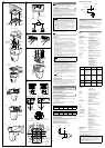
Connection
Connecting to the Network
Connect the LAN port of the camera unit to a router or hub in the network using
the network cable (straight, not supplied).
To connect to a computer
Connect the LAN port of the camera unit to the network connector of a
computer using the network cable (cross, not supplied).
Connecting the Power Source
Connect the 12 V DC or 24 V AC power supply system to the power input
terminal on the rear of the camera.
Use the 12 V DC or 24 V AC power source isolated from the 100 to 240 V AC.
The usable voltage range is as follows:
12 V DC: 10.8 to 13.2 V
24 V AC: 21.6 to 26.4 V
Use the UL cable (VW-1 style 1007) for 12 V DC or 24 V AC connection.
Recommended power cable
12 V DC
Cable(AWG)
#24(0.22 mm) #22(0.33 mm) #20(0.52 mm) #18(0.83 mm)
Maximumcable
length(m (feet))
4.5 (14.8) 7.5 (24.6) 12 (39) 21 (69)
24 V AC
Cable(AWG)
#24(0.22 mm) #22(0.33 mm) #20(0.52 mm) #18(0.83 mm)
Maximumcable
length(m (feet))
10.5 (34) 16.5 (54) 27.5 (90) 45.5 (149)
Connecting the I/O Cable
Using the I/O receptacle
While holding down the button on the slot to which you want to connect the
wire (AWG No. 28 to 22) with a small slotted screwdriver, insert the wire into the
slot. Then release the screwdriver from the button.
Repeat this procedure to connect all required wires.
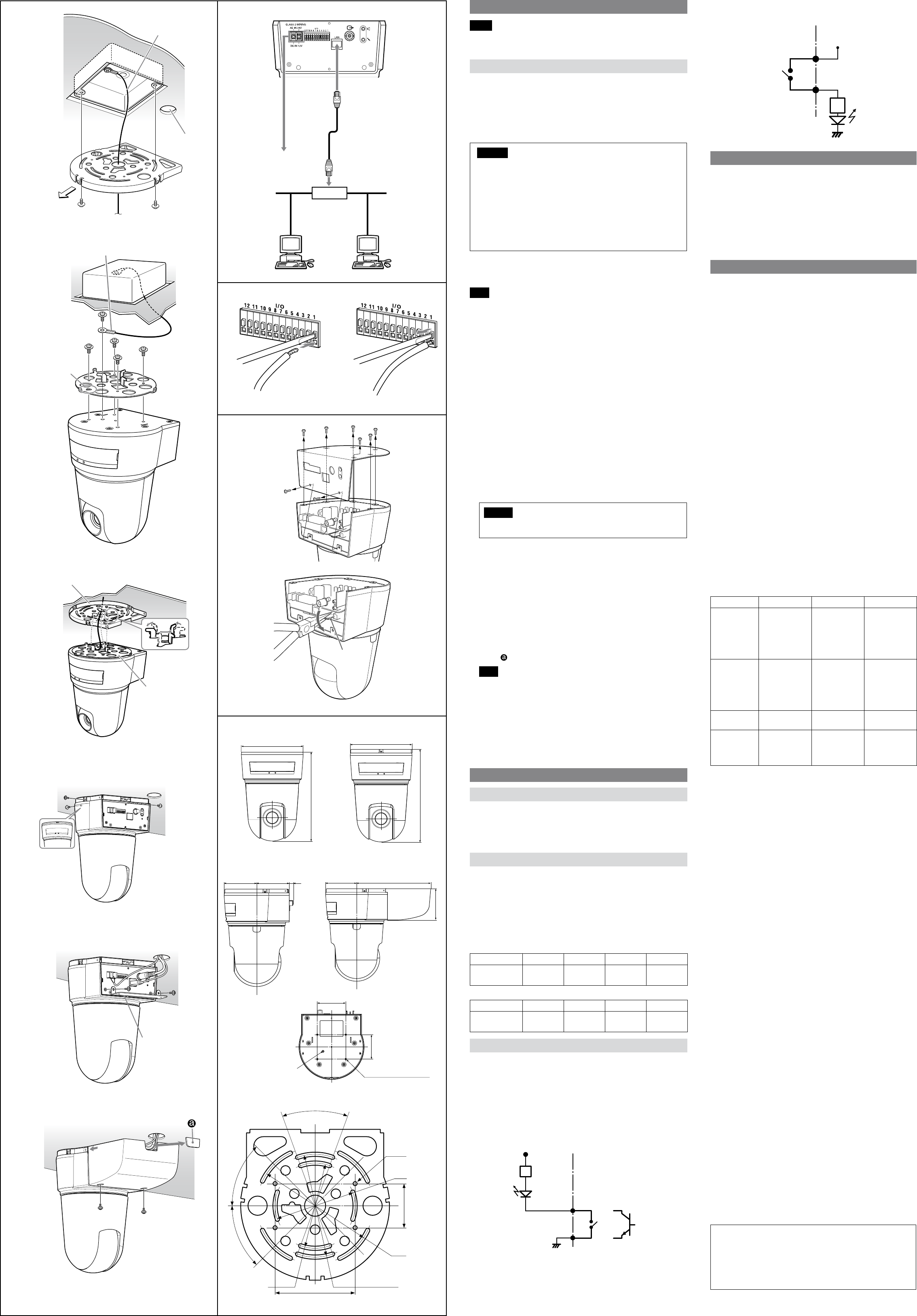
Wiring diagram for sensor input
Mechanical switch/open collector output device
Camera inside
5 V
2.35 kohms
1 or 3 pin
(Sensor In +)
2 or 4 pin (GND)
GND
Mechanical
switch
Open collector
output device
Outside
or
Wiring diagram for alarm output
Camera inside
5 or 7 pin
(Alarm Output +)
Magnet relay
24 V AC/24 V DC, 1 A
or less
6 or 8 pin
(Alarm Output –)
Outside
5 V
Circuit example
R
GND
When You Discard the Camera
For environmental reasons, take out the lithium battery from the camera and
discard it appropriately.
1 Remove the eight screws and detach the bottom panel.
2 Hold the board on which the lithium battery is attached using long-nose
pliers. Then, bend it in the direction of the arrow illustrated to detach the
battery.
WARNING (for service personnel only)
There is danger of explosion if batteries are mishandled.
Dispose of batteries properly in accordance with the manufacturer’s
instructions and all applicable local regulations.
Specications
Network
Protocol TCP/IP, ARP, ICMP, HTTP, FTP (server/client), SMTP
(client), DHCP (client), DNS (client), NTP
(client), SNMP (MIB-2), RTP/RTCP
Compression
Video compression format JPEG/MPEG4/H.264
Audio compression format G.711/G.726 (40,32,24,16 kbps)
Image size 640 × 480 (VGA), 384 × 288, 320 × 240 (QVGA),
160 × 120 (QQVGA)
Maximum frame rate SNC-RX570N/RX550N/RX530N: 30 fps
SNC-RX570P/RX550P/RX530P: 25 fps
Web browser Internet Explorer Ver. 6.0 or later
Available OS Microsoft Windows 2000, Windows XP, Windows
Vista
Computer environments CPU: Pentium 4, 1.5 GHz or higher (Pentium 4,
2.4 GHz or higher recommended)
RAM: 256 MB or more
Display size: 1024 × 768 or more
Maximum user access 20 users
Network security Password (basic authentication),
IP ltering
Homepage customization Starting from a homepage in the built-in ash
memory, an ATA memory card or a “Memory
Stick” possible
Other functions Detection, image trimming, built-in clock, etc.
Camera
Signal system SNC-RX570N/RX550N/RX530N: NTSC color
system
SNC-RX570P/RX550P/RX530P: PAL color system
Image device 1/4 type color CCD
Total picture elements:
SNC-RX570N/RX550N/RX530N:
Approx. 410,000
SNC-RX570P/RX550P/RX530P:
Approx. 470,000
Eective picture elements:
SNC-RX570N/RX550N/RX530N:
Approx. 380,000
SNC-RX570P/RX550P/RX530P:
Approx. 440,000
SNC-RX570N/P SNC-RX550N/P SNC-RX530N/P
Lens
36x (Optical), 12x
(Digital)
f=3.4 to 122.4
mm, F1.6 to 4.5
Horizontal angle:
1.7° to 57.8°
26x (Optical), 12x
(Digital)
f=3.5 to 91 mm,
F1.6 to 3.8
Horizontal angle:
2.2° to 54.2°
18x (Optical), 12x
(Digital)
f=4.1 to 73.8 mm,
F1.4 to 3.0
Horizontal angle:
2.8° to 48°
Minimum
object distance
TELE end:
1,500 mm (59
1/8 inches)
WIDE end:
320 mm
(12 5/8 inches)
TELE end:
1,500 mm (59
1/8 inches)
WIDE end:
320 mm
(12 5/8 inches)
TELE end: 800 mm
(31 1/2 inches)
WIDE end:
290 mm
(11 1/2 inches)
Minimum
illumination
1.4 lx (F1.6/50 IRE) 1 lx (F1.6/50 IRE) 0.7 lx (F1.4/50 IRE)
Horizontal
resolution
NTSC: 530 TV
(WIDE end)
PAL: 530 TV (WIDE
end)
NTSC: 470 TV
(WIDE end)
PAL: 460 TV (WIDE
end)
NTSC: 470 TV
(WIDE end)
PAL: 460 TV (WIDE
end)
Shutter speed 1 to 1/10,000 s
Video S/N 50 dB or more
Mechanism
Pan 360º, endless rotation
Maximum speed: 300° / s
Tilt –90° to 0°
Maximum speed: 300° / s
Interface
Network port 10BASE-T/100BASE-TX, auto negotiation (RJ-45)
I/O port Sensor input : × 2, make contact
Alarm output : × 2, 24 V AC/DC, 1 A
(mechanical relay outputs electrically
isolated from the camera)
Serial interface: ×1 (RS-232C)
Video output VIDEO OUT: BNC, 1.0 Vp-p,
75 ohms, unbalanced, sync negative
PC card slot PCMCIA Type II
Memory Stick slot “Memory Stick”
Microphone input Minijack (monaural)
Plug-in-power supported (rated voltage: 2.5 V
DC)
Recommended load impedance 2.2 khoms
Line output Minijack (monaural), Maximum output level: 1
Vrms
Others
Power supply 12 V DC ± 10%
24 V AC ± 10%, 50/60 Hz
Power consumption 25 W max.
Operating temperature 0 °C to +50 °C (32 °F to 122 °F)
Storage temperature –20 °C to +60 °C (–4 °F to +140 °F)
Operating humidity 20 to 80 %
Storage humidity 20 to 95 %
Dimensions 230 × 160 × 160 mm (9 1/8 × 6 3/8 × 6 3/8
inches) (h/w/d)
not including the projecting parts
Mass Approx. 2.3 kg (4 lb 14 oz)
Supplied accessories CD-ROM (User’s Guide and supplied programs)
(1)
Upper ceiling bracket (1)
Lower ceiling bracket (1)
Cable cover (1)
Cable cover mounting bracket (1)
Screws
M3 × 8 (11)
Screw
M4 × 8 (1)
Fall-prevention wire rope (1)
Installation Manual (this document) (1)
B&P Warranty Booklet (1) (SNC-RX570N/RX550N/
RX530N only)
Optional accessories
Wireless card SNCA-CFW1, SNCA-CFW5*
Wireless LAN antenna SNCA-AN1
“Memory Stick” MSX-1GS (1GB), MSX-512S (512MB), MSH-128
(128MB)
* SNCA-CFW5 is not available in some countries and areas. For details, contact
your authorized Sony dealer.
Design and specications are subject to change without notice.
Regular parts replacement
Some of the parts that make up this product (electrolytic condenser, for
example) need replacing regularly depending on their life expectancies.
The lives of parts dier according to the environment or condition
in which this product is used and the length of time it is used, so we
recommend regular checks.
Consult the dealer from whom you bought it for details.
1, 2
3
4
5
6, 7
8
1
2
Front of the
camera
Upper ceiling
bracket
Ceiling
Ceiling
Lower ceiling
bracket
M4×8
(supplied)
M3×8
(supplied)
Set the triangular
hole at the front
of the camera.
Upper ceiling
bracket
Lower ceiling
bracket
Ceiling
Ceiling
M3×8
(supplied)
Ceiling
Cable cover
mounting bracket
Ceiling
M3×8
(supplied)
Camera (rear)
LAN
Network cable
(straight, not supplied)
10BASE-T/
100BASE-TX
Hub
Network
to 12 V DC
or 24 V AC
Slotted
screwdriver
Wire
Lithium
battery
Front
Bottom
Unit: mm (inches)
Side (with ceiling brackets)
46 (1
15
/
16
)
Hole 4 – M3 (×4)
160 (6
3
/
8
)
160 (6
3
/
8
)
230 (9
1
/
8
)
242 (9
5
/
8
)
Front (with ceilling brackets)
80 (3
1
/
4
) 80 (3
1
/
4
) 80 (3
1
/
4
) 191 (7
5
/
8
)10 (
13
/
32
)
83 (3
3
/
8
)
Side (with cable cover)
70 (2
7
/
8
)
Screw hole for
wire rope
83.5 (3
3
/
8
)
ø83.5 (3
3
/
8
)
Hole width
4.4 (
3
/
16
) (×2)
Hole 4 –
ø4.4 (
3
/
16
)
40°
(Adjustable range:±20°)
45°
Upper ceiling bracket
Fall-prevention
wire rope
Hole for
connecting cables
Fall-prevention wire rope
M3×8
(supplied)
45°
ø88.9 (3
1
/
2
)
Hole width
4.4 (
3
/
16
) (×4)
ø121.2 (4
7
/
8
)
Hole width
4.4 (
3
/
16
) (×4)
ø107.3 (4
1
/
4
)
Hole width
4.4 (
3
/
16
) (×4)
60 (2
3
/
8
)