


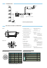

CONNECTIONS
LO-77ERK
VCL-08YM
VCL-12YM
VCL-16YM
VCL-25YM
XC-ST30/CE
XC-ST50/CE
Tripod adaptor
VCT-ST70I
CCXC-12P02N
C mount lens
Extension ring kit
VCL-50YM
AC
VIDEO OUT
VS
*2
HD/VD
*1
TRIG
WEN
DC +12 V
VIDEO OUT
VS*
2
HD/VD*
1
Camera cable
Camera adaptor
DC-700/CE
New EIAJ standard 12 pin assignment
Junction box
JB-77
Trigger IN connector not available
CCXC-12P05N
CCXC-12P10N
CCXC-12P25N
*
1
: HD/VD cannot be simultaneously used with VS
*
2
: VS cannot be simultaneously used with HD/VD
LOCATION OF PARTS & OPERATION
4 5
2
1
3
2
3
A
5
B0 9
4
8
67
CCD
VIDEO CAMERA MODULE
XC-ST50
4 12 pin
multi-connector
1 Lens mount (C mount)
A commercial C mount lens as well as
Sony standard lenses can be used.
2 Camera fixing reference hole
High-precision screw hole machined
on the lens mount surface.
3 Screw hole for tripod adaptor
installation (VCT-ST70I)
4 12 pin multi-connector
The 12 pin multi-connector is
connected to a DC IN/SYNC
(DC power/sync signal input)
5 BNC connector
Video out
6 Gamma correction
ON/OFF switchable
7 Internal/External
synchronization switch
In the EXT position, if there is no
external sync input, the internal sync is
activated inside the camera.
In this case, HD/VD signal is not output
through the 12 pin multi-connector.
8 Trigger polarity switch
The trigger polarity is selectable
(neg/pos polarity)
9 75 Ω termination switch
0 Dip switch
Dip switch 1 - 4: Shutter speed
Dip switch 5: FRAME/FIELD exposure
Dip switch 6 - 8: Normal shutter mode,
External trigger shutter
mode, restart/reset mode
A Gain switch
A: Image output at a fixed level of
image according to the brightness
of the subject. (Variable range: 0 to
18 dB)
F: Fixed gain 0 dB
M:gain (manual)
Factory setting: the variable gain is adjusted to
the fixed sensitivity for a
standard subject. When using
two or more XC-ST50/50CE,
XC-ST30/30CE cameras,
identical images of the same
subject can be attained.
B Gain control
The gain can be adjusted between 0 to
18 dB when the gain switch is set to "M".
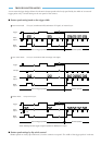
Pin No. External HD/VD sync Internal HD/VD sync External VS sync
1 GND GND GND
2 +12 V +12 V +12 V
3 GND GND GND
4 VIDEO output VIDEO output VIDEO output
5 GND GND GND
6
External HD input Internal HD output
-
7
*3
External VD input Internal VD output
VS
8 GND GND GND
9
---
10
*4
WEN output
*2
WEN output
*2
WEN output
11 TRIG input TRIG input TRIG input
12 GND GND GND
*3
: In restart/reset mode VD input is necessary
*4
: WEN output is only effective in EXT trigger shutter mode
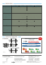
No. Switch Factory setting
6 Gamma correction ON/OFF OFF
7 Internal/External sync EXT
8 Trigger polarity +
9 75 Ω termination ON
0 Dip switch
1·2·3·4: Shutter speed OFF
5: Field/Frame OFF
6·7·8:
normal shutter/EXT trigger shutter/restart reset
OFF
A GAIN FIX
● Rear Panel Factory settings
● Side
● 12 pin multi-connector
● Rear Panel