


Overview
6
Location and Function
of Parts and Operation
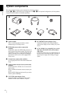
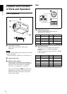
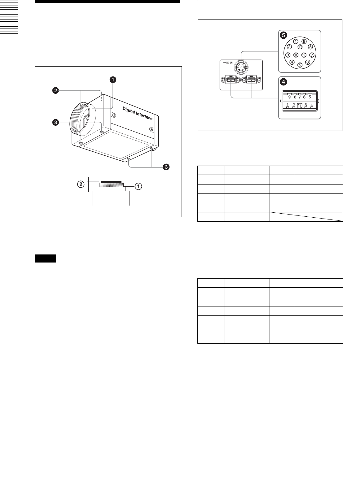
Front/Top/Bottom
1 Lens mount (C-mount)
Attach any C-mount lens or other optical
equipment.
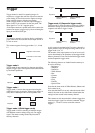
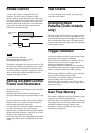
Note
The lens must not project more than 10 mm (13/32 inch)
from the lens mount.
1 Lens mount face 210 mm (13/32 inch) or less
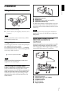
2 Auxiliary holes (top)
3 Reference holes (bottom)
These precision screw holes are for locking the
camera module. Locking the camera module into
these holes secures the optical axis alignment.
For details, see “Dimensions” on page 38.
Four screw reference holes 3 can be used as the
tripod adaptor screw holes, too. Screw the VCT-
ST70I tripod adaptor into the four screw holes
when you use a tripod.
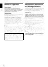
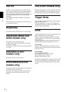
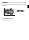
Rear
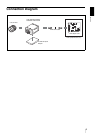
4 IEEE1394b connectors
Connect an IEEE1394b camera cable (not
supplied) to this connector.
5 12-pin I/O connector
When power from the IEEE1394b connector is
insufficient, power is supplied through this
connector.
Connect a camera cable such as the CCXC-12P05N
to this connector.
Pin No. Signal Pin No. Signal
1TPB– 6VG
2TPB+ 7NC
3TPA– 8VP
4TPA+ 9TPBG
5TPAG
Pin No. Signal Pin No. Signal
1 Power GND 7 GPIO IN 2
2 Power IN 8 GPIO OUT 2–
3 ISO GND 9 GPIO OUT 2+
4 Strobe OUT 10 GPIO IN 1
5 GPIO OUT 1– 11 Trigger IN
6 GPIO OUT 1+ 12 ISO GND