8
Mode Setting
Specifications of the Trigger
Pulse
• Input impedance; 10 kΩ or more.
• The voltage and pulse width used are measured at pin
11 of a 12-pin multi-connector on the rear panel.
• If you set the trigger pulse with the DIP switches, use
the 100
µ
s to 1/4 sec pulse width.
Setting the external shutter speed with the trigger
pulse width
Set all DIP switches (1 to 4 on the rear panel) to 0.
You can obtain an arbitrary shutter speed by setting the
trigger pulse width to the range of 2
µ
sec to 250 msec.
Exposure time = Trigger pulse width + 97
µ
sec (EIA)
Trigger pulse width + 120
µ
sec (CCIR)
Notes
• The DIP switch 5 position is optional. (The field
setting is recommended.) The field setting can obtain
a sensitivity that is twice that of the frame setting.
• If you input a new trigger pulse before the video
signal output for the previous trigger pulse is output
completely, an incorrect video signal will be output.
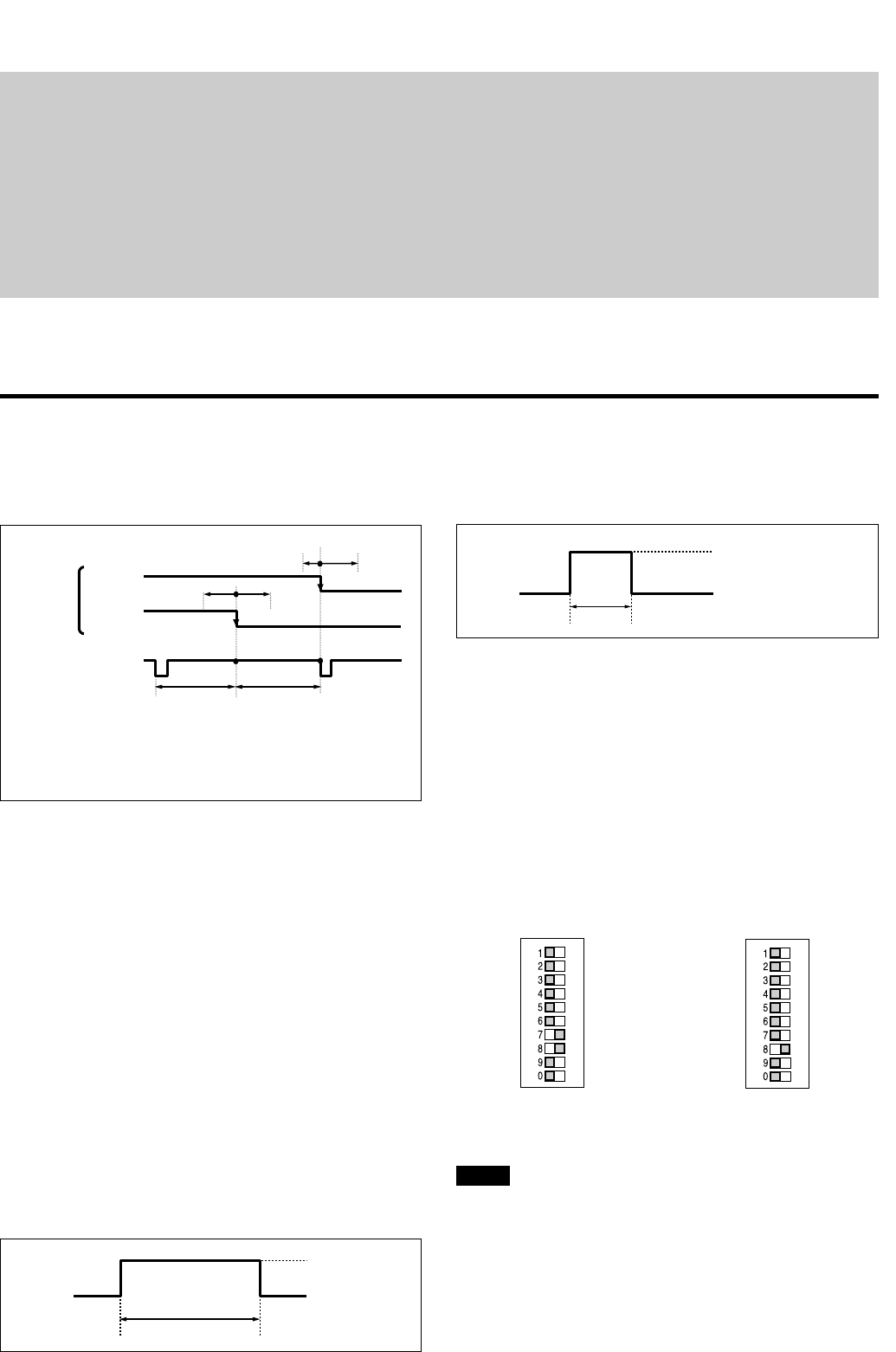
Mode 1 (Non-reset mode) Mode 2 (Reset mode)
Specifications of the Input/Output
Unit: Clock
1Clk=69.84 nsec (EIA)
70.48 nsec (CCIR)
Make sure that the external HD/VD phases against the
standard central phase are as shown in the figure
above. Invalid signal input may cause an error in the
internal reset.
When you restart/reset the camera or operate the
camera by inputting an external trigger shutter pulse,
the Vsync signal for the image is output 1 H later from
the external VD.
Normal:
HD/VD continuous (EIA/CCIR frequencies:
Maintained. Timing: See the above figure.)
Restart/Reset and /External trigger shutter
HD continuous/VD (Reset): Any timing if the phase
with HD is within the above range.
Specifications of the WEN
Output
The amplitude level is the typical value when
terminated with 10 kΩ.
External
VD
External HD
EVEN,
Non Interlace
ODD
Mode Setting
2005
100 200
455 (454) 455 (454)
( ): CCIR
4.5 V
0 V
250 H(EIA)
293 H(CCIR)
Input Phase Specifications of
the External HD/VD
2
µ
sec
to
1/4 sec
4 to 5.0 V
0 to 1.0 V


