


A
B
C
1
1
DC
Owner’s Record
The model and serial numbers are located on the bottom.
Record the serial number in the space provided below. Refer
to these numbers whenever you call upon your Sony dealer
regarding this product.
Model No. _____________ Serial No. ______________
WARNING
To reduce the risk of fire or electric shock, do not
expose this apparatus to rain or moisture.
To avoid electrical shock, do not open the cabinet.
Refer servicing to qualified personnel only.
AVERTISSEMENT
Afin de réduire les risques d’incendie ou
d’électrocution, ne pas exposer cet appareil à la
pluie ou à l’humidité.
Afin d’écarter tout risque d’électrocution,
garder le coffret fermé. Ne confier l’entretien de
l’appareil qu’à un personnel qualifié.
WARNUNG
Um die Gefahr von Bränden oder elektrischen
Schlägen zu verringern, darf dieses Gerät nicht
Regen oder Feuchtigkeit ausgesetzt werden.
Um einen elektrischen Schlag zu vermeiden, darf
das Gehäuse nicht geöffnet werden. Überlassen
Sie Wartungsarbeiten stets nur qualifiziertem
Fachpersonal.
경고
화재나 감전 위험을 방지하려면 장치가 물기나
습기에 노출되지 않도록 하십시오.
감전 위험이 있으므로 본체를 열지 마십시오. 자격
있는 전문 정비 요원만 서비스를 실시해야 합니다.
WARNING
This unit has no power switch.
When installing the unit, incorporate a readily accessible disconnect device in the
fixed wiring, or connect the power plug to an easily accessible socket-outlet near
the unit. If a fault should occur during operation of the unit, operate the disconnect
device to switch the power supply off, or disconnect the power plug.
AVERTISSEMENT
Cet appareil ne possède pas d’interrupteur d’alimentation.
Lors de l’installation de l’appareil, incorporer un dispositif de coupure dans le
câblage fixe ou brancher la fiche d’alimentation dans une prise murale facilement
accessible proche de l’appareil. En cas de problème lors du fonctionnement de
l’appareil, enclencher le dispositif de coupure d’alimentation ou débrancher la fiche
d’alimentation.
WARNUNG
Dieses Gerät hat keinen Netzschalter.
Beim Einbau des Geräts ist daher im Festkabel ein leicht zugänglicher Unterbrecher
einzufügen, oder der Netzstecker muss mit einer in der Nähe des Geräts befindlichen,
leicht zugänglichen Wandsteckdose verbunden werden. Wenn während des Betriebs
eine Funktionsstörung auftritt, ist der Unterbrecher zu betätigen bzw. der Netzstecker
abzuziehen, damit die Stromversorgung zum Gerät unterbrochen wird.
경고
이 기기에는 전원 스위치가 없습니다.
기기를 설치할 때 접근이 용이한 스위치를 고정된 배선에 만들어 사용하거나
벽면 콘센트에 전원 플러그를 연결합니다. 이때 콘센트가 기기 근처에 있어야
하고 전원 코드의 접근이 용이해야 합니다. 기기를 조작하는 동안 오류가
발생하면 스위치를 OFF하거나 전원 플러그를 뽑으십시오.
IMPORTANT
The nameplate is located on the bottom.
IMPORTANT
La plaque signalétique se situe sous l’appareil.
WICHTIG
Das Namensschild befindet sich auf der Unterseite des Gerätes.
중요
명판은 바닥에 있습니다.
CMOS
CMOS
CMOS
CMOS
B
(
)
CMOS
IEEE1394b
IEEE1394b
C
PC PCI
IEEE1394b
DC-700
AC
8 I/O
C
C
C
C 10 mm
10 mm
English
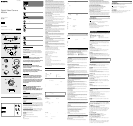
When Installing the Camera A
When you install the camera with various peripheral devices and if the devices have
different ground electric potential, ground only one device. In case there is an ground
electric potential difference, the camera may be damaged.
-1 Basic configuration /
-2 Optional configuration
IEEE1394b connector
8-pin I/O connector
Host device (e.g., PC)
Abnormal electricity
Ground electric potencial difference
Power supply unit (DC-700/700CE)
Notes on Operation
Power supply
Power is supplied to the camera module via the IEEE1394b cable connected to a PC.
If the power supply is insufficient, use the DC-700/700CE that supplies stable power
with less ripple or noise.
Foreign bodies
Be careful not to spill liquids, or drop any flammable or metal objects in the camera
body.
Locations for operation and storage
Avoid operation or storage in the following places.
Extremely hot or cold locations. Recommended temperature range is 0
C to
40
C (32
F to 104
F)
Locations subject to strong vibration or shock
Near generators of strong electromagnetic radiation such as TV or radio
transmitters
Care
Use a blower to remove dust from the surface of the lens or optical filter. Clean the
exterior with a soft, dry cloth.
If the camera is very grimy, apply a cloth soaked in a mild detergent then wipe with a
dry cloth. Do not apply organic solvents such as alcohol which may damage the finish.
Note on laser beams
Laser beams may damage a CMOS sensor. You are cautioned that the surface of
a CMOS sensor should not be exposed to laser beam radiation in an environment
where a laser beam device is used.
Overview
The XCD-MV6 is a monochrome digital camera module.
IEEE1394b connector
The camera module can output a digital image with a transfer speed of 1600 Mbps.
The camera module is equipped with one IEEE 1394b (beta) connector.
High resolution
The camera module uses a high-image-quality CMOS sensor to produce high-
resolution image output.
Using the VGA-compatible CMOS sensor, the XCD-MV6 outputs a digital image at 60
frames per second.
The use of the square-pixel CMOS sensor also eliminates the need to convert aspect
ratios during image processing.
External trigger function
You can operate the shutter at any timing by synchronizing the shutter with the
external trigger signals.
Electronic shutter
You can select the exposure time from a variety of settings. This allows you to capture
an image under optimal conditions.
8-pin I/O connector
When power from the IEEE1394b connector is insufficient, power is supplied through
the 8-pin connector. The 8-pin connector is also used for a trigger input and strobe
output, and as a general-purpose I/O port.
Low power consumption
The power consumption is decreased to 2.2 W for the XCD-MV6 with 12 V DC input.
Body fixing
The mounting screw holes are provided in the reference plane on the lower surface of
the body, allowing mounting with the absolute minimum deviation of the optical axis.
Phenomena Specic to CMOS Image Sensors
The following phenomena that may appear in images are specific to CMOS
(Complementary Metal Oxide Semiconductor) image sensors. They do not indicate
malfunctions.
White flecks
Although the CMOS image sensors are produced with high-precision technologies,
fine white flecks may be generated on the screen in rare cases, caused by cosmic rays,
etc.
This is related to the principle of CMOS image sensors and is not a malfunction.
The white flecks especially tend to be seen in the following cases:
when operating at a high environmental temperature
when you have raised the gain (sensitivity)
when the slow shutter or trigger cycle is long
Aliasing
When fine patterns, stripes, or lines are shot, they may appear jagged or flicker.
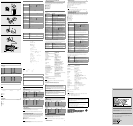
System Components B
The camera module imaging system comprises the following products. Products
to are used for the basic configuration, and to for the optional configuration.
(All the products except the camera module are available separately.)
Camera module
This is a small-size, high-resolution, camera module using a CMOS image sensor.
For the customers in the U.S.A.
This equipment has been tested and found to comply with the limits for a Class A
digital device, pursuant to Part 15 of the FCC Rules. These limits are designed to
provide reasonable protection against harmful interference when the equipment
is operated in a commercial environment. This equipment generates, uses, and can
radiate radio frequency energy and, if not installed and used in accordance with
the instruction manual, may cause harmful interference to radio communications.
Operation of this equipment in a residential area is likely to cause harmful interference
in which case the user will be required to correct the interference at his own expense.
You are cautioned that any changes or modifications not expressly approved in this
manual could void your authority to operate this equipment.
All interface cables used to connect peripherals must be shielded in order to comply
with the limits for a digital device pursuant to Subpart B of Part 15 of FCC Rules.
This device complies with Part 15 of the FCC Rules. Operation is subject to the
following two conditions: (1) this device may not cause harmful interference, and (2)
this device must accept any interference received, including interference that may
cause undesired operation.
For the customers in Canada
This Class A digital apparatus complies with Canadian ICES-003.
Pour les clients au Canada
Cet appareil numérique de la classe A est conforme à la norme NMB-003 du Canada.
A급 기기(업무용 방송통신기자재)
이 기기는 업무용(A급)전자파적합기기로서 판매자 또는 사용자는 이 점을
주의하시기 바라며, 가정외의 지역에서 사용하는 것을 목적으로 합니다.
For the customers in Europe
The manufacturer of this product is Sony Corporation, 1-7-1 Konan, Minato-ku, Tokyo,
Japan.
The Authorized Representative for EMC and product safety is Sony Deutschland
GmbH, Hedelfinger Strasse 61, 70327 Stuttgart, Germany.
Pour les clients en Europe
Le fabricant de ce produit est Sony Corporation, 1-7-1 Konan, Minato-ku, Tokyo, Japon.
Le représentant autorisé pour EMC et la sécurité des produits est Sony Deutschland
GmbH, Hedelfinger Strasse 61, 70327 Stuttgart, Allemagne.
Für Kunden in Europa
Der Hersteller dieses Produkts ist Sony Corporation, 1-7-1 Konan, Minato-ku, Tokyo,
Japan.
Der autorisierte Repräsentant für EMV und Produktsicherheit ist Sony Deutschland
GmbH, Hedelfinger Strasse 61, 70327 Stuttgart, Deutschland.
For the customers in Europe, Australia and New Zealand
WARNING
This is a Class A product. In a domestic environment, this product may cause radio
interference in which case the user may be required to take adequate measures.
In the case that interference should occur, consult your nearest authorized Sony
service facility.
Pour les clients en Europe, Australie et Nouvelle-Zélande
AVERTISSEMENT
Il s’agit d’un produit de Classe A. Dans un environnement domestique, cet appareil
peut provoquer des interférences radio, dans ce cas l’utilisateur peut être amené à
prendre des mesures appropriées.
Si des interférences se produisent, contactez votre service après-vente agréé Sony.
Für Kunden in Europa, Australien und Neuseeland
WARNUNG
Dies ist eine Einrichtung, welche die Funk-Entstörung nach Klasse A besitzt. Diese
Einrichtung kann im Wohnbereich Funkstörungen verursachen; in diesem Fall kann
vom Betreiber verlangt werden, angemessene Maßnahmen durchzuführen und dafür
aufzukommen.
Sollten Funkstörungen auftreten, wenden Sie sich bitte an den nächsten autorisierten
Sony-Kundendienst.
This apparatus shall not be used in the residential area.
Ne pas utiliser cet appareil dans une zone résidentielle.
Dieser Apparat darf nicht im Wohnbereich verwendet werden.
모델명: XCD-MV6
승인된 상표명: Sony EMCS Corp.
제조사/제조 국가: Sony EMCS Corp. (일본)
인증신청인 식별부호: MKM
A/S 센터
공신테크노소닉 주식회사
서울시 양청구 목동 923-14 현대드림타워빌딩 4층
전화: 02-785-3441
팩스: 02-785-3450
다이트론코리아 주식회사
서울시 구로구 구로동 197-28 이앤씨벤처드림타워 6차 703호
전화: 02-6910-3336
팩스: 02-6910-3399
Note: This camera is not intended for use in security applications in the meaning of
the European standard series EN 50132 (Alarm systems - CCTV surveillance systems for
use in security applications).
A
-1
-2
IEEE1394b
8 I/O
PC
DC-700
PC IEEE1394b
DC-700
0
C 40
C
CMOS
CMOS
XCD-MV6
IEEE1394b
1600 Mbps IEEE1394b 1
CMOS
XCD-MV6 VGA CMOS 60
CMOS
8 I/O
IEEE1394b 8
8 I/
O
XCD-MV6 2.2 W DC 12 V
CMOS
4-270-402-
02
(1)
© 2010 Sony Corporation Printed in Japan
Operating Instructions
사용 설명서
XCD-MV6
–1
–2
Digital Video Camera
Module
/ Camera /
카메라
/ Camera /
카메라
IEEE1394b camera cable (commercially available)
Connect this cable to the IEEE1394b connector on the rear panel of the camera
module. The power and image/control signals are transmitted through this cable. To
prevent a poor connection or damage to the camera or cable, use the cable equipped
with fixing screws. As the camera module is equipped with a beta connector, be sure
to use a beta-connector-compatible cable.
C-mount lens (commercially available)
Use an appropriate lens for the camera module and usage.
Camera module interface board (commercially available)
Install the board in a PCI bus slot of a host device such as a PC.
Select an IEEE1394b interface board to match your system.
DC-700/700CE camera adaptor (Sony)
Connect this adaptor to the camera module to enable power supply from an ordinary
AC power source.
Camera cable (commercially available)
Connect this cable to the 8-pin I/O connector on the rear panel of the camera module.
The cable is used for power supply and exchange of trigger signals. For details on a
suitable cable, consult your local dealer or nearest authorized Sony service facility.
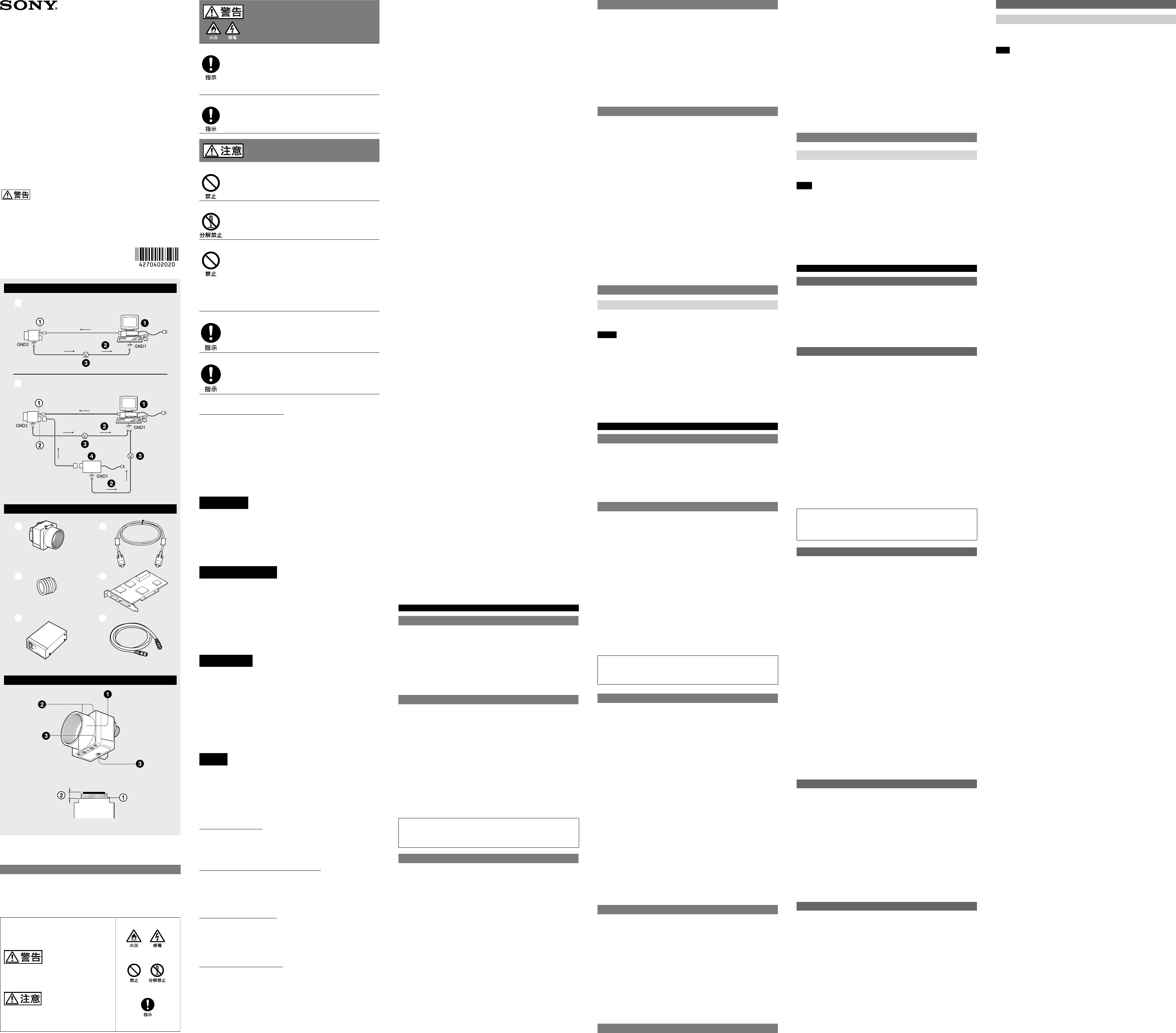
Location and Function of Parts and Operation
Front/Top/Bottom C
Lens mount (C-mount)
Attach any C-mount lens or other optical equipment.
Note
The lens must not project more than 10 mm (13/32 inch) from the lens mount.
Lens mount face 10 mm (13/32 inch) or less
Auxiliary holes (top)
Reference holes (bottom)
These precision screw holes are for locking the camera module. Locking the camera
module into these holes secures the optical axis alignment.
For details, refer to the Technical Manual.
한국어
카메라를 설치할 때 A
카메라를 다양한 주변 장치와 함께 설치할 경우 주변 장치의 접지 전위가 서로
다르면 한 장치만 접지하십시오. 접지 전위에 차이가 있으면 카메라가 손상될 수
있습니다.
-1 기본 구성 /
-2 선택 사양 구성
IEEE1394b 커넥터
8핀 I/O 커넥터
호스트 장치(예: PC)
비정상적인 전력
접지 전위차
전원 공급 장치 (DC-700/700CE)
사용시 주의점
전원 공급 장치
전원은 PC에 연결된 IEEE1394b 케이블을 통해 카메라 모듈에 공급됩니다.
전원 공급이 불충분할 경우 파동과 노이즈가 적으며 안정적인 전원을 공급하는
DC-700/700CE를 이용하십시오.
이물질
카메라 본체에 액체를 쏟거나 인화물질 또는 금속 물체를 떨어뜨리지 않도록
주의하십시오.
사용 및 보관 장소
다음 장소에서는 사용하거나 보관하지 마십시오.
너무 덥거나 추운 장소. 권장되는 사용 온도는 0 ℃에서 40 ℃사이입니다.
강한 진동이나 충격이 발생하는 장소
TV나 무선 송신기와 같이 강력한 전자기가 방사되는 발전기 주변
관리 방법
블로워를 사용하여 렌즈나 광학 필터의 표면에 있는 먼지를 제거하십시오.
부드러운 마른 헝겊으로 제품의 외부를 닦아 주십시오.
카메라가 심하게 더러워진 경우 순한 세제를 적신 천으로 닦은 다음 마른 천으로
닦아 내십시오. 표면 처리에 손상을 줄 수 있는 알코올과 같은 같은 유기 용제는
사용하지 마십시오.
레이저 광선 참고사항
레이저 광선은 CMOS 센서를 손상시킬 수 있습니다. 레이저 광선 장치가
사용되는 환경에서 CMOS 센서 표면이 레이저 광선 방사선에 노출되지
않도록 주의하십시오.
개요
XCD-MV6은 단색 디지털 카메라 모듈입니다.
IEEE1394b 커넥터
카메라 모듈은 1600 Mbps의 속도로 디지털 이미지를 출력할 수 있습니다. 한
개의 IEEE 1394b(베타) 커넥터로 카메라 모듈이 부착됩니다.
높은 해상도
카메라 모듈은 고화질의 CMOS 센서를 사용하여 고해상도의 이미지를
출력합니다.
XCD-MV6은 VGA 호환 CMOS 센서를 사용하여 초당 60 프레임의 속도로
디지털 이미지를 출력합니다.
CMOS 센서가 정사각 픽셀의 CMOS이므로 변환 과정을 거치지 않고 원본의
가로세로비를 사용하여 이미지를 처리할 수 있습니다.
외부 트리거 기능
외부 트리거 신호와 셔터를 동기화하여 원하는 때에 셔터를 작동할 수 있습니다.
전자식 셔터
여러 가지 설정 중에서 노출 시간을 선택할 수 있습니다. 이를 통해 최적의
조건에서 이미지를 캡처할 수 있습니다.
8핀 I/O 커넥터
IEEE1394b 커넥터로부터의 전력이 충분치 못한 경우 8핀 커넥터를 통해
전력이 공급됩니다. 8핀 커넥터는 트리거 입력 및 스트로브 출력에도 사용되며
범용 I/O 포트로도 사용됩니다.
낮은 전력 소비
전원 소비는 12 V DC 입력에서 2.2 W로 감소됩니다.
본체 고정
고정 나사 구멍이 본체 하부면의 기준면에 있어 광학 축의 절대편차를 최소
수준으로 줄일 수 있습니다.
CMOS 센서 특유의 현상
이미지에 다음의 현상이 나타날 수 있으나 이는 CMOS 센서 특유의 현상으로
제품에 문제가 있는 것이 아닙니다.
백색 반점
CMOS 센서는 정밀 기술로 제작되었으나 간혹 우주선 노출 등과 같은 원인으로
화면에 미세한 반점이 생길 수도 있습니다.
이는 CMOS 센서의 원리와 관련된 것으로 고장이 아닙니다.
이러한 백색 반점은 특히 다음과 같은 경우 쉽게 발생됩니다.
높은 온도에서 카메라를 사용하는 경우
게인(감도)을 높인 경우
느린 셔터 속도를 사용한 경우 또는 트리거 사이클이 긴 경우
앨리어싱
미세 패턴, 줄무늬 또는 라인을 찍으면 들쭉날쭉하거나 가물가물하게 찍힐 수
있습니다.
시스템 구성 부품 B
카메라 모듈 이미지 시스템은 다음과 같은 제품으로 구성됩니다. 제품
에서
까지는 기본 구성이고
에서
까지는 선택사양 구성입니다. (카메라 모듈을
제외한 제품들은 별도로 구매 가능합니다.)
카메라 모듈
CMOS 센서를 사용하는 소형의 고해상도 카메라 모듈입니다.
IEEE1394b 카메라 케이블(별매품)
이 케이블을 카메라 모듈 후면 패널의 IEEE1394b 커넥터에 연결합니다. 이
케이블을 통해 전력 및 이미지/제어 신호가 전달됩니다. 연결 불량이나 카메라
또는 케이블 손상을 방지하려면 고정 나사가 있는 케이블을 사용하십시오.
카메라 모듈에 베타 커넥터가 부착되므로 베타 커넥터 호환 케이블에
연결하십시오.
C-마운트 렌즈(별매품)
카메라 모듈 및 용도에 맞는 적절한 렌즈를 사용합니다.
카메라 모듈 인터페이스 보드(별매품)
PC와 같은 호스트 장치의 PCI 버스 슬롯에 이 보드를 설치합니다.
시스템에 맞는 IEEE1394b 인터페이스보드를 선택합니다.
DC-700/700CE 카메라 어댑터(Sony)
이 어댑터를 카메라 모듈에 연결하여 일반 AC 전원에서 전력을 공급받을 수
있습니다.
카메라 케이블(별매품)
이 케이블을 카메라 모듈 후면 패널의 8핀 I/O 커넥터에 연결합니다. 케이블은
전원 공급 및 트리거 신호 교환에 사용됩니다. 적합한 케이블에 대한 내용은
근처 대리점이나 공인 Sony 서비스 센터에 문의하십시오.
부품 위치와 기능 및 사용법
앞면/윗면/밑면 C
렌즈 마운트(C-마운트)
C-마운트 렌즈 또는 기타 광학 장비를 부착하십시오.
참고
렌즈는 렌즈 마운트에서 10 mm 이상 돌출해서는 안됩니다.
렌즈 마운트면
10 mm 이하
맞춤 구멍(윗면)
기준 구멍(밑면)
이들 정밀한 나사 구멍들은 카메라 모듈을 고정하는 데 사용됩니다. 카메라
모듈을 이 구멍들에 고정하여 광학 축을 정렬할 수 있습니다.
자세한 내용은 기술 설명서를 참조하십시오.