


About the Technical Manual
The Operating Instructions describe the functions and use of this product.
For more details, see the Technical Manual. Please ask your sales representative
about the Technical Manual.
기술 설명서에 대하여
사용 설명서는 본 제품의 기능 및 사용에 대해 설명합니다.
자세한 내용은 기술 설명서를 참조하십시오. 기술 설명서에 대해서는
담당 영업 사원에게 문의하시기 바랍니다.
D
IEEE1394b
IEEE1394b
1 TPB 6 VG
2 TPB
7 NC
3 TPA
8 VP
4 TPA
9 TPBG
5 TPAG
12 I/O
IEEE1394b
CCXC-12P05N
1 7 GPIO 2
2
8 GPIO 2
3 ISO 9 GPIO 2
4 10 GPIO 1
5 GPIO
1 11
6 GPIO 1 12 ISO
E
1
2
F
VCT-ST70I
4.5 mm 5.5 mm 0.18 0.22
G
IEEE1394b IEEE1394b 1394b
IEEE1394b
IEEE1394b
IEEE1394b
IEEE1394b IEEE1394b
English
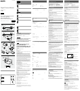
Rear D
IEEE1394b connectors
Connect an IEEE1394b camera cable (not supplied) to this connector.
Pin No. Signal Pin.No. Signal
1 TPB– 6 VG
2 TPB+ 7 NC
3 TPA– 8 VP
4 TPA+ 9 TPBG
5 TPAG
12-pin I/O connector
When power from the IEEE1394b connector is insufficient, power is supplied through
this connector.
Connect a camera cable such as the CCXC-12P05N to this connector.
Pin No. Signal Pin.No. Signal
1 Power GND 7 GPIO IN 2
2 Power IN 8 GPIO OUT 2-
3 ISO GND 9 GPIO OUT 2+
4 Strobe OUT 10 GPIO IN 1
5 GPIO OUT 1- 11 Trigger IN
6 GPIO OUT 1+ 12 ISO GND
Installation
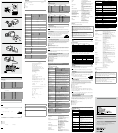
Fitting the lens E
1 Remove the lens mount cap.
2 Screw in the lens (not supplied), and turn it until it is secured.
Note
Clean the optical filter with a commercially available blower brush to remove dust.
Using a tripod F
To use the tripod, install the VCT-ST70I tripod adaptor (not supplied) on the camera
module.
Use a tripod screw with a protrusion () extending from the installation surface, as
follows, and tighten the screw using a hand screwdriver.
: 4.5 mm to 5.5 mm (0.18 inches to 0.22 inches)
Note
When you install the tripod adaptor, use the screws supplied with the tripod adaptor.
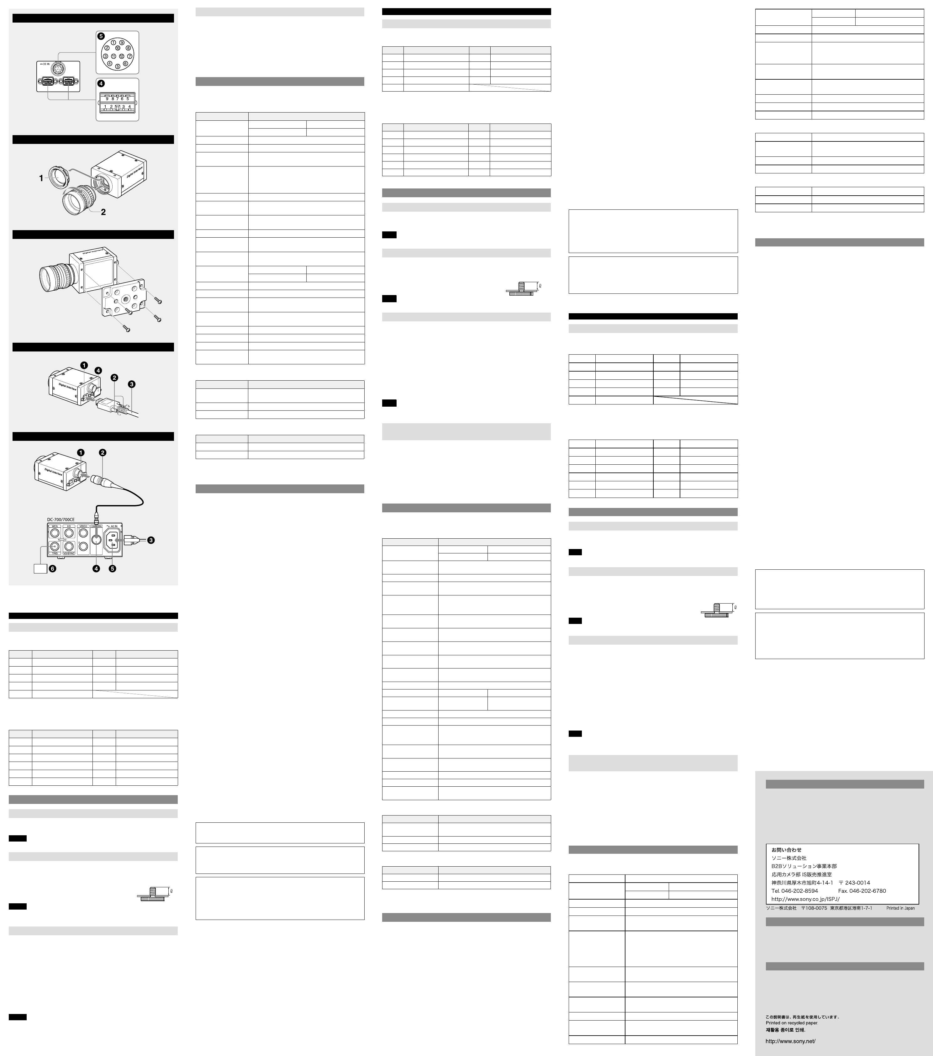
Connecting the camera cable G
Connect a commercially available IEEE1394b camera cable to the IEEE1394b connector
and the 1394b interface connector of your PC. When you connect the cable, insert
the cable connector into the IEEE1394b connector until it snaps into place, holding it.
Then, tighten the fixing screws placed on both sides of the cable connector.
IEEE1394b connector
Fixing screws
IEEE1394b camera cable (not supplied)
IEEE1394b connector cap
The IEEE1394b connector on the right has a cover cap exclusively for this camera. If
you use this connector, remove the cap. The unused connector shall be covered with
the cap.
Note
Loose fixing screws may cause a poor connection or damage to the camera or cable.
Be sure to tighten the fixing screws.
When power supply from the IEEE1394b
H
connector is insufficient
Power can be supplied to the camera module via the DC-700/700CE camera adaptor
(optional) and a camera cable such as CCXC-12P05N (optional) if power supply from
the IEEE1394b connector is insufficient.
12-pin I/O connector
Camera cable (e.g. CCXC-12P05N)
to AC power source
CAMERA connector
AC IN connector
Trigger generator
Controlling the Camera from Your PC
You can control the camera from your PC. The following table shows the control
functions.
Functions common to all models
Control functions Description
Gain Color model 0 dB to +18 dB
Black and white model 0 dB to +24 dB
Shutter
Setting the shutter speed between 1/100,000 sec. and
16 sec.
Brightness Pedestal level adjustable
Gamma Customizing the gamma curve using 1,024 gamma
tables (10 bits) (IIDC extended function)
Trigger
Mode 0 (control by register) and Mode 1 (control by pulse
width) supported for hardware trigger/software trigger
Broadcast commands supported for software trigger
Strobe Out Setting the delay from the exposure start and the pulse
width by register value
AutoExposure Keeping a constant average image level by the image
level detection and feedback to gain and shutter
AutoExposure Detection
Frame Setting
Setting the detection area for Auto Exposure
GPIO Assigning GPIO (General-Purpose Input/Output) to the
12-pin connector
MemoryShot Saving an image to the built-in frame memory and
reading the saved image from the memory
ISO Enable (Video Start) Starts transmitting an image in continuous mode
OneShot/MultiShot OneShot Transmitting an image
MultiShot Transmitting the specified
number of images
DataDepth Indicating the effective bit length in 16-bit mode
CameraInitialize Resetting the camera to the default features
MemoryChannel PresetMemory0 (factory default status) and 1 user
available memory channel /15 user available memory
channels selectable
1394 Bus Synchronization Defining the exposure timing in synchronization with
the cycle time register of 1394 bus
TriggerDelay Specifying the delay time after which the received
trigger becomes effective
PartialScan Partition by a unit of 32 lines x 24 pixels available
UserFreeMemory A 256-byte user available memory provided
Bulk Mode Acquiring images continuously by changing the
settings in memory channels
XCD-V60CR/SX90CR/U100CR (color models) only
Control functions Description
WhiteBalance (Raw mode) Adjusting the R and B levels individually
Auto white balance, One Push white balance available
G Gain Adjusting the G gain
OpticalFilter Switching the Bayer pattern
XCD-V60/SX90/U100 (black and white models) only
Control functions Description
3 x 3 Filter Switching the 3 x 3 filter
Sharpness Adjusting the image contour strength
These control items comply with Digital Camera Protocol, Ver. 1.31, of the IEEE1394
Standard. For more details, refer to the Technical Manual.
Specifications
Pickup device Progressive scan IT CCD
XCD-V60CR/V60/SX90CR/SX90: 1/3 type
XCD-U100CR/U100: 1/1.8 type
Interface IEEE1394b – 2002
Output signal format (horizontal/vertical)
XCD-V60CR/V60: 640 x 480 (VGA)
XCD-SX90CR/SX90: 1,280 x 960 (SXGA)
XCD-U100CR/U100: 1,600 x 1,200 (UXGA)
Frame rate XCD-V60CR/V60: 90 fps
XCD-SX90CR/SX90: 30 fps
XCD-U100CR/U100: 15 fps
Transfer speed 800/400 Mbps
External trigger signal (conditions) Pulse width: 10 μs or more
Polarity: Negative
Amplitude: 5 V to 24 V DC
Lens mount C-mount
Flange back 17.526 mm
Minimum illumination XCD-V60CR/SX90CR/U100CR: 20 lx (F1.4,
Gain: +18 dB)
XCD-V60/SX90/U100: 2 lx (F1.4, Gain: +24 dB)
IEEE1394b H
IEEE1394b DC-700
CCXC-12P05N
12 I/O
CCXC-12P05N
AC
CAMERA
AC IN
0 dB +18 dB
0 dB +24 dB
1/100,000 16
1,024 10
IIDC
/ Mode0
Mode1
GPIO 12 GPIO
ISO Enable
OneShot/MultiShot OneShot 1
MultiShot
DataDepth 16
CameraInitialize
PresetMemory0
1 ch/15 ch
1394 1394
32 x 24
256
XCD-V60CR/SX90CR/U100CR
Raw
R B
/
G G
XCD-V60/SX90/U100
3 x 3 3 x 3
IEEE1394 Ver.1.31
IT CCD
XCD-V60CR/V60/SX90CR/SX90: 1/3
XCD-U100CR/U100: 1/1.8
IEEE1394b – 2002
XCD-V60CR/V60: 640 x 480 VGA
XCD-SX90CR/SX90: 1,280 x 960 SXGA
XCD-U100CR/U100: 1,600 x 1,200 UXGA
XCD-V60CR/V60: 90 fps
XCD-SX90CR/SX90: 30 fps
XCD-U100CR/
U100: 15 fps
800/400 Mbps
10 s
DC 5 V 24 V
C
17.526 mm
XCD-V60CR/SX90CR/U100CR: 20 lx
(F1.4 Gain: +18 dB)
XCD-V60/SX90/U100: 2 lx (F1.4 Gain: +24 dB)
= 1 LUT
XCD-V60CR/SX90CR/U100CR: 0 dB +18 dB
XCD-V60/SX90/U100: 0 dB +24 dB
1/100,000 16
IEEE1394b 12
DC +8 V +30 V
XCD-V60CR/V60/SX90CR/SX90: 2.8 W DC 12 V
XCD-U100CR/U100: 3.0 W DC 12 V
0 +40
5 45
30 60
20 80 ( )
20 95 ( )
10 G (20 Hz 200 Hz )
70 G
44 W 33 H 57.5 D mm
140 g
1
IEEE1394b 1
1
A
VCCI-A
OneShot/MultiShot OneShot 단일 이미지 전송
MultiShot 지정된 수의 이미지의 전송
DataDepth 16 비트 모드로 유효 비트 길이 표시
CameraInitialize 기본 기능으로 카메라 재설정
MemoryChannel PresetMemory0(공장 기본 설정 상태) 및 한
개의 사용자 이용 가능 메모리 채널 /15개의 사용자
이용 가능 메모리 채널의 선택 가능
1394 버스 동기화 1394 버스의 사이클 시간 등록으로 동기화에서
노출 시간 규정
TriggerDelay 수신된 트리거가 유효하게 되기까지의 지연 시간
지정
PartialScan 32 라인 × 24 픽셀 단위로 분할 스캔 가능
UserFreeMemory 256바이트 사용자 이용 가능 메모리 제공
벌크 모드 메모리 채널의 설정 변경으로 지속적인 이미지 획득
XCD-V60CR/SX90CR/U100CR(컬러 모드) 전용
제어 기능 설명
WhiteBalance
(원시 모드)
R 및 B 레벨 개별 조정
오토 화이트 밸런스, 원 푸시 화이트 밸런스 가능
G 게인 G 게인 조정
OpticalFilter 베이어 패턴 전환
XCD-V60/SX90/U100(흑백 모드) 전용
제어 기능 설명
3 × 3 필터 3 × 3 필터 전환
선명도 이미지 윤곽선 강도 조정
이 제어 항목을 IEEE1394 표준 1.31 버전의 디지털 카메라 프로토콜을 따르고
있습니다. 자세한 내용은 기술 설명서를 참조하십시오.
사양
픽업 장치 프로그래시브 스캔 IT CCD
XCD-V60CR/V60/SX90CR/SX90: 1/3형
XCD-U100CR/U100: 1/1.8형
인터페이스 IEEE1394b - 2002
출력 신호 형식(수평/수직) XCD-V60CR/V60: 640 × 480(VGA)
XCD-SX90CR/SX90: 1,280 × 960(SXGA)
XCD-U100CR/U100: 1,600 × 1,200(UXGA)
프레임 속도 XCD-V60CR/V60: 90 fps
XCD-SX90CR/SX90: 30 fps
XCD-U100CR/U100: 15 fps
전송 속도 800/400 Mbps
외부 트리거 신호(조건) 펄스 폭: 10 μs 이상
극성: 네거티브
진폭: 5 V 에서 24 V DC
렌즈 마운트 C-마운트
플랜지 백 17.526 mm
최저 조도 XCD-V60CR/SX90CR/U100CR: 20 lx
(F1.4, 게인: +18 dB)
XCD-V60/SX90/U100: 2 lx(F1.4, 게인:
+24 dB)
감마 γ= 1(LUT에 의해 선택 가능)
게인 XCD-V60CR/SX90CR/U100CR: 0 dB 에서
+18 dB, 오토 게인
XCD-V60/SX90/U100: 0 dB 에서 +24 dB,
오토 게인
셔터 속도 1/100,000초 에서 16초, 자동 셔터
전원 IEEE1394b 카메라 케이블 또는 12핀 카메라
케이블로부터 +8 V 에서 +30 V DC 전원 공급
소비 전력 XCD-V60CR/V60/SX90CR/SX90: 2.8 W
(12 V DC 입력)
XCD-U100CR/U100: 3.0 W(12 V DC 입력)
성능 보증 온도 0
C 에서 +40
C
작동 온도 -5
C 에서 +45
C
보관 온도 -30
C 에서 +60
C
작동시 상대 습도 20% 에서 80%(이슬맺힘 없음)
보관시 상대 습도 20% 에서 95%(이슬맺힘 없음)
내진동성 10 G(기준 구멍 사용시 20 Hz 에서 200 Hz)
내충격성 70 G
외부 크기(너비/높이/길이) 44 × 33 × 57.5 mm(돌출부 미포함)
중량 140 g
부속품 렌즈 마운트 캡(1)
IEEE1394b 커넥터 캡(1)
사용 설명서(1)
디자인 및 사양은 예고 없이 변경될 수 있습니다.
중요
명판은 바닥에 있습니다.
주의
사용 전에는 항상 정상적으로 작동하는지 확인하십시오.
SONY는 본체의 오류로 인한 현재 또는 장래 이익의 손실에 대한 손해에
대해서 보증기간 중이거나 보증기간 경과 후 또는 어떠한 이유에도 상관없이
배상이나 변상에 대한 일체의 책임을 지지 않습니다.
정기적 부품 교환
본 제품을 구성하는 부품 중 일부(예: 전기 컨덴서)는 부품의 예상 내구
수명에 따라 정기적인 교환을 필요로 할 수 있습니다.
부품의 수명은 본 제품이 사용되는 환경이나 조건 또는 사용 시간에 따라
다르므로 정기적으로 점검하시기 바랍니다.
자세한 내용은 제품을 구매하신 대리점에 문의하시기 바랍니다.
Gamma γ= 1 (selectable by LUT)
Gain XCD-V60CR/SX90CR/U100CR: 0 dB to
+18 dB, Auto gain
XCD-V60/SX90/U100: 0 dB to +24 dB, Auto
gain
Shutter speed 1/100,000 seconds~16 seconds, Auto
shutter
Power +8 V to +30 V DC from IEEE1394b camera
cable or camera cable with 12-pin
connector
Power consumption XCD-V60CR/V60/SX90CR/SX90: 2.8 W (12 V
DC input)
XCD-U100CR/U100: 3.0 W (12 V DC input)
Performance guaranty temperature 0 °C to +40 °C (32 °F to 104 °F)
Operating temperature –5 °C to +45 °C (23 °F to 113 °F)
Storage temperature –30 °C to +60 °C (–22 °F to 140 °F)
Operating relative humidity 20% to 80% (no condensation)
Storage relative humidity 20% to 95% (no condensation)
Vibration resistance 10 G (20 Hz to 200 Hz, at using the
reference holes)
Shock resistance 70 G
External dimension (w/h/d)
44 × 33 × 57.5 mm (1
3
/
4
× 1
3
/
16
× 2
3
/
8
inches),
not including projecting parts
Mass 140 g (4 oz)
Accessories Lens mount cap (1)
IEEE1394b connector cap (1)
Operating Instructions (1)
Design and specifications are subject to change without notice.
IMPORTANT
The nameplate is located on the bottom.
Note
Always verify that the unit is operating properly before use. SONY WILL NOT
BE LIABLE FOR DAMAGES OF ANY KIND INCLUDING, BUT NOT LIMITED TO,
COMPENSATION OR REIMBURSEMENT ON ACCOUNT OF THE LOSS OF PRESENT
OR PROSPECTIVE PROFITS DUE TO FAILURE OF THIS UNIT, EITHER DURING THE
WARRANTY PERIOD OR AFTER EXPIRATION OF THE WARRANTY, OR FOR ANY OTHER
REASON WHATSOEVER.
Regular parts replacement
Some of the parts that make up this product (electrolytic condenser, for example)
need replacing regularly depending on their life expectancies.
The lives of parts differ according to the environment or condition in which this
product is used and the length of time it is used, so we recommend regular checks.
Consult the dealer from whom you bought it for details.
한국어
뒷면 D
IEEE1394b 커넥터
IEEE1394b 카메라 케이블(별매품)을 이 커넥터에 연결합니다.
핀 번호 신호 핀 번호 신호
1 TPB- 6 VG
2 TPB+ 7 NC
3 TPA- 8 VP
4 TPA+ 9 TPBG
5 TPAG
12핀 I/O 커넥터
IEEE1394b 커넥터로부터의 전력이 충분치 못한 경우 이 커넥터를 통해 전력이
공급됩니다.
CCXC-12P05N과 같은 카메라 케이블을 이 커넥터에 연결합니다.
핀 번호 신호 핀 번호 신호
1 전원 GND 7 GPIO IN 2
2 전원 IN 8 GPIO OUT 2-
3 ISO GND 9 GPIO OUT 2+
4 스트로브 OUT 10 GPIO IN 1
5 GPIO OUT 1- 11 트리거 IN
6 GPIO OUT 1+ 12 ISO GND
설치
렌즈 부착 E
1
렌즈 마운트 캡을 제거합니다.
2
렌즈(별매품)를 끼우고 완전히 고정될 때까지 돌립니다.
참고
시판 중인 블로워 브러시를 사용하여 광학 필터에 있는 먼지를 제거하십시오.
삼각대 사용 F
삼각대를 사용하려면 카메라 모듈에 VCT-ST70I 삼각대 어댑터(별매품)를
설치하십시오.
다음과 같이 설치면에서 (
)만큼 돌출되는 삼각대용 나사를 사용하고 나사
드라이버를 사용하여 나사를 고정합니다.
: 4.5 mm 에서 5.5 mm (0.18 인치 에서 0.22 인치)
참고
삼각대 어댑터를 설치할 때는 함께 제공된 나사를 사용하십시오.
카메라 케이블 연결 G
시판 IEEE1394b 카메라 케이블을 IEEE1394b 커넥터와 PC의 1394b
인터페이스 커넥터에 연결합니다. 케이블을 연결할 때는 제자리에 끼워져
고정될 때까지 케이블 커넥터를 IEEE1394b 커넥터에 꽂습니다. 그런 다음
케이블 커넥터의 양측에 있는 고정 나사를 조입니다.
IEEE1394b 커넥터
고정 나사
IEEE1394b 카메라 케이블(별매품)
IEEE1394b 커넥터 캡
오른쪽에 있는 IEEE1394b 커넥터에는 이 카메라에만 사용되는 커버 캡이
있습니다. 이 커넥터를 사용할 경우 캡을 분리하십시오. 사용하지 않는 커넥터는
분리한 캡으로 끼워야 합니다.
참고
느슨하게 나사를 조이면 연결 상태가 불량하거나 카메라 또는 케이블이 손상될
수 있습니다. 고정 나사를 올바로 조이도록 하십시오.
IEEE1394b 커넥터로부터의 전원
H
공급이 충분치 않은 경우
IEEE1394b 커넥터로부터의 전력이 충분치 않은 경우 DC-700/700CE 카메라
어댑터(선택 사양) 및 CCXC-12P05N(선택 사양)과 같은 카메라 케이블을
통해 카메라 모듈로 전원을 공급할 수 있습니다.
12핀 I/O 커넥터
카메라 케이블(예: CCXC-12P05N)
AC 전원
CAMERA 커넥터
AC IN 커넥터
트리거 발생기
PC에서 카메라 제어
PC에서 카메라를 제어할 수 있습니다. 다음 표는 제어 기능을 정리한 것입니다.
전모델에 공통적인 제어 기능
제어 기능 설명
게인 컬러 모델 0 dB 에서 +18 dB
흑백 모델 0 dB 에서 +24 dB
셔터 셔터 속도를 1/100,000초 과 16초 사이로 설정
밝기 페데스탈 레벨 조정
감마 1,024 감마 테이블(10비트)(IIDC 확장 기능)을
사용하여 감마 커브 사용자 정의
트리거 하드웨어 트리거/소프트웨어 트리거를 위해
지원되는 모드 0(레지스터로 제어) 및 모드 1(펄스
폭으로 제어) 지원
소프트웨어 트리거를 위해 지원되는 브로드캐스트
커맨드 지원
스트로브 Out 노출 시작부터 지연 및 레지스터 값에 의한 펄스
폭설정
AutoExposure 이미지 레벨 감지, 게인과 셔터에 대한 피드백으로
일정한 평균 이미지 레벨 유지
AutoExposure 감지
프레임 설정
자동 노출을 위한 감지 영역 설정
GPIO GPIO(범용 I/O)를 12핀 커넥터로 할당
MemoryShot 내장 프레임 메모리에 이미지 저장 및 메모리에
저장된 이미지 판독
ISO 활성(비디오 시작) 연속 모드에서 이미지 전송 시작
D
E
F
G
H