


D
About the Technical Manual
The Operating Instructions describe the functions and use of this
product.
For more details, see the
Technical Manual. Please ask your sales
representative about the
Technical Manual.
E
F
6
45
7
61
54321
10
9876
15 14 13 12 11
43
25
1
3
7
89
6
4
5
5
2
D
1
C
C
C 7 mm
1 2
7 mm
2
3
3
4
4
VCT-ST70I
E
4
RS-232C 6
PC
E
-
4
1 TXD 4 NC
2 RXD 5 NC
3
6NC
5
15
UXGA
E
-
5
UXGA
1R 9NC
2G 10
3B 11 NC
4NC 12NC
5 13 HD
6 14 VD
7 15 NC
8
6
DC IN DC 12
CCXC-12P05N DC 12 V
No.
E
-
6
1 7NC
2DC12 V 8
3 9NC
4NC 10
5 11
6NC 12
7
DIGITAL IF 26
26
No.
E
-
7
1
INNER_SHIELD ( )
14
INNER_SHIELD ( )
2X0 ( )15X0 ( )
3X1 ( )16X1 ( )
4X2 ( )17X2 ( )
5 XCLK ( )18XCLK ( )
6X3 ( )19X3 ( )
7 Ser TC ( )20Ser TC ( )
8 Ser TFG ( )21Ser TFG ( )
9 TRIG ( ) 22 TRIG ( )
10 NC 23 NC
11 NC 24 NC
12 NC 25 NC
13
INNER_SHIELD ( )
26
INNER_SHIELD ( )
26
2
LVDS 3.3 V IC
9 TRIG ( )
22
TRIG ( )
F
DC IN
RS-232C
1
DC IN
2
DIGITAL IF
3 4
5 6
7 8
9
RS-232C
DC-700
PC
PC
/
1
1
/
10000
:
1
/
15
1
/
10000
0 +18 dB
OFF/ON
OFF/ON
OFF/ON
26 /DC-700
/ /AWB
XCL-U1000C
OFF/ON
XCL-U1000C
VCT-ST70I
4
ISO
4
4.5 mm 0.2 mm
ASA
4
0.197
CCD
CCD
CCD
CCD
1/1.8 CCD
1628 1236
CCD 18.75 kHz
CCD
36.0 MHz
4.4 4.4 m
8.5 6.8 mm
C
17.526 mm
XCL-U1000C: LVDS R/G/B 8
: 235
: 16
XCL-U1000: LVDS 10
: 940
: 64
: 700 mV
HD
: 75 kHz
VD : 60 Hz
15 Hz
1600 1200 /
XCL-U1000C: 2,000 lx F8
XCL-U1000: 400 lx
F5.6
XCL-U1000C: 4 lx : +18 dB F1.4
XCL-U1000: 2 lx : +18 dB F1.4
0 18 dB
OFF/ON
XCL-U1000C: /
XCL-U1000: / /
OFF/ON
XCL-U1000C
/ /AWB
XCL-U1000C
OFF/ON
1 1/10000
DC 12 V
:
10.5 15 V
5.5 W
5 45
30 60
20 80
20 95
10 G 20 Hz 200 Hz
70 G
56 W 44 H 95 D mm
250 g
1
1
VCCI
B
Location and Function of Parts and Operation
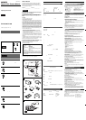
Front/Top/Bottom Fig. D
1 Lens mount (C-mount)
Attach any C-mount lens or other optical equipment.
Note
The lens must not project more than 7 mm (9/32 inch) from the lens mount.
1 Lens mount face 2 7 mm (9/32 inch) or less
2 Reference holes (Top)
3 Reference holes/Tripod screw holes (bottom)
These precision screw holes are for locking the camera module. Locking
the camera module into these holes secures the optical axis alignment.
For details, refer to the User’s Guide.
You can install the camera on a tripod. To install on a tripod, you will need
to install a tripod adaptor VCT-ST70I to the camera on the reference holes
3.
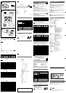
Rear Fig. E
4 RS-232C connector (6-pin)
You can connect a serial cable to this connector to control a camera module
from a camera control device (e.g., PC).
(For details on the pin arrangement, see Figure E-4.)
Pin
Signal
Pin
Signal
No. No.
1 TXD 4 NC
2 RXD 5 NC
3 Ground 6 NC
5 Monitor output connector (15-pin)
You can connect a monitor cable to this connector to display an image on a
multiscan monitor supporting UXGA resolution.
(For details on the pin arrangement, see Figure E-5.)
Note
If you connect a multiscan monitor that does not support UXGA resolution,
an image may not be displayed.
Pin
Signal
Pin
Signal
No. No.
1R output 9 NC
2G output 10 Ground
3B output 11 NC
4NC 12NC
5 Ground 13 HD output
6 Ground 14 VD input
7 Ground 15 NC
8 Ground
6 DC IN (DC power input) connector (12-pin)
You can connect a CCXC-12P05N camera cable to input the +12 V DC
power supply. The pin configuration of this connector is as follows.
(For details on the pin arrangement, see Figure E-6.)
Pin
Signal
Pin
Signal
No. No.
1 Ground 7 NC
2 +12 V DC 8 Ground
3 Ground 9 NC
4NC10Exposure pulse output
5 Ground 11 Triger pulse input
6NC12Ground
7 DIGITAL IF (Interface) connector (26-pin)
You can connect a Camera Link cable to this connector to control a camera
module from a host device utilizing the serial communication protocol while
outputting a video signal from the camera module. You can input the
external trigger signal via the 26-pin connector and operate a camera
module in the external trigger mode. The pin configuration of this connector
is as follows.
(For details on the pin arrangement, see Figure E-7.)
Pin No. Digital signal Pin No. Digital signal
1 INNER_SHIELD (Ground) 14 INNER_SHIELD (Ground)
2X0– output (Signal) 15 X0+ output (Signal)
3X1– output (Signal) 16 X1+ output (Signal)
4X2– output (Signal) 17 X2+ output (Signal)
5 XCLK– output (Signal) 18 XCLK+ output (Signal)
6X3– output (Signal) 19 X3+ output (Signal)
7 Ser TC+ (Signal) 20 Ser TC– (Signal)
8 Ser TFG– (Signal) 21 Ser TFG+ (Signal)
9 TRIG– input (Signal) 22 TRIG+ input (Signal)
10 NC 23 NC
11 NC 24 NC
12 NC 25 NC
13 INNER_SHIELD (Ground) 26 INNER_SHIELD (Ground)
Note
When you operate a camera module by inputting an external trigger signal
via the 26-pin connector, make sure to input external trigger signals that
meet the following specifications to both the two pins.
Specifications for the External Trigger Signal
Amplitude: LVDS using a 3.3 volt IC
Connections: Input a TRIG (–) signal to the 9th pin.
Input a TRIG (+) signal to the 22nd pin.
Connecting the cables Fig. F
Connect the camera cable to the DC IN connector and the Camera Link
cable to the digital interface cable respectively. Also, if needed, connect the
monitor cable to the monitor output connector and the serial cable to the
RS-232C connector respectively. When you connect the Camera Link cable
or monitor cable, turn the two fastening screws on the connector to secure
the cable tightly.
1 DC IN connector 2 Digital interface connector
3 Camera cable 4 Camera Link cable
5 Fastening screws 6 Serial cable
7 Monitor cable 8 Monitor output connector
9 RS-232C connector
Connect the other end of the camera cable to the DC-700 / 700CE and the
other end of the Camera Link cable to the camera module interface board.
Also, if needed, connect the other end of the monitor cable to the monitor
and the other end of the serial cable to the camera control device.
Controlling the camera from the host device
You can control the camera from host devices such as a PC. The following
table shows the control functions.
Control functions Description
Operating mode
Normal/Trigger
Shutter speed Normal 1 –
1
/
10000
Trigger
Internal setting:
1
/
15
–
1
/
10000
Setting by trigger pulse width
Gain 0 to +18 dB
Binning function OFF/ON
Partial Scan function
OFF/ON
Detail OFF/ON
External trigger input
26-pin connector / DC-700 / 700CE
White balance Preset/Manual/AWB
(XCL-U1000C only)
Matrix OFF/ON
(XCL-U1000C only)
Note
Make sure to supply power to the camera module and confirm that the
camera module is operating before inputting a trigger signal. If you input
external signals to a camera module without the power supplied, this may
cause a mulfunction of the camera module.
Using a tripod
To use the tripod, install the tripod adaptor VCT-ST70I (not supplied) on the
camera module.
Use a tripod screw with a protrusion (4) extending
from the installation surface, as follows:
ISO standard: Length 4.5 mm ±0.2 mm
ASA standard: Length 0.197 inches
Note
If you install a tripod adapter (not supplied), use the screws provided.
1
2
3
2
1
4
4
100% VOC ( )
Printed on 100% recycled paper using VOC (Volatile Organic
Compound)-free vegetable oil based ink.
Typical CCD Phenomena
The following effects on the monitor screen are characteristic of CCD
cameras. They do not indicate any fault with the camera module.
Smear
This occurs when shooting a very bright object such as electric lighting, the
sun, or a strong reflection.
This phenomenon is caused by an electric charge induced by infrared
radiation deep in the photosensor. It appears as a vertical smear, since the
CCD imaging element uses an interline transfer system.
Vertical aliasing
When you shoot vertical stripes or lines, they may appear jagged.
Blemishes
A CCD image sensor consists of an array of individual sensor elements
(pixels). A malfunctioning sensor element will cause a single pixel blemish
in the picture. (This is generally not a problem.)
White speckles
When you shoot a dark object at a high temperature, small white dots may
appear all over the image.
Note
If strong light enters a wide area of the screen, the screen may become
dark. This is not a malfunction. If this occurs, avoid strong light or adjust the
lens iris to reduce the light amount.
Specifications
Imaging system
Pickup device Progressive scan 1/1.8 type CCD
Effective picture elements (horizontal/vertical)
1628 × 1236
CCD vertical drive frequency
18.75 kHz
CCD horizontal drive frequency
36.0 MHz
Cell size (horizontal/vertical)
4.4 × 4.4 µm
Chip size (horizontal/vertical)
8.5 × 6.8 mm
Optical system and others
Lens mount C-mount
Flange focal length 17.526 mm
Synchronization Internal
Video output Digital output
XCL-U1000C: R/G/B 8 bits LVDS
Reference video output level: 235 steps
Reference pedestal level: 16 steps
XCL-U1000: 10 bits LVDS
Reference video output level: 940 steps
Reference pedestal level: 64 steps
Monitor output (analog output)
Reference video output level: 700 mV
HD frequency: 75 kHz positive
VD frequency: 60 Hz positive
Output signal frequency
15 Hz
Effective lines 1600 × 1200 (horizontal/vertical)
Sensitivity XCL-U1000C: 2,000 lx, F8
XCL-U1000: 400 lx, F5.6
Minimum illumination XCL-U1000C: 4 lx (gain: +18 dB, F1.4)
XCL-U1000: 2 lx (gain: +18 dB, F1.4)
Gain 0 to +18 dB
γ OFF/ON
Read mode XCL-U1000C: normal/high rate scan
XCL-U1000: normal/binning/high rate scan
Detail OFF/ON
White balance (XCL-U1000C only):
preset/manual/AWB
Matrix (XCL-U1000C only):
OFF/ON
Shutter External trigger shutter
Shutter speed 1 ~ 1/10000 sec.
Power +12 V DC (Range: +10.5 to 15 V)
Power consumption 5.5 W
Operating temperature: –5 to +45°C (23 to 113°F)
Storage temperature: –30 to +60°C (–22 to 140°F)
Operating relative humidity:
20 to 80% (no condensation)
Storage relative humidity:
20 to 95% (no condensation)
Vibration resistance 10 G (20 Hz to 200 Hz)
Shock resistance 70 G
External dimension (w/h/d)
56 × 44 × 95 mm
(2 1/4 × 1 3/4 × 3 3/4 inches)
Mass 250 g (9 oz)
Accessories Lens mount cap (1)
Operating Instructions (1)
Design and specifications are subject to change without notice.
IMPORTANT
The nameplate is located on the bottom.
Polarity: positive