


6
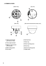
mark
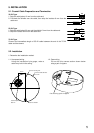
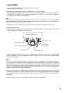
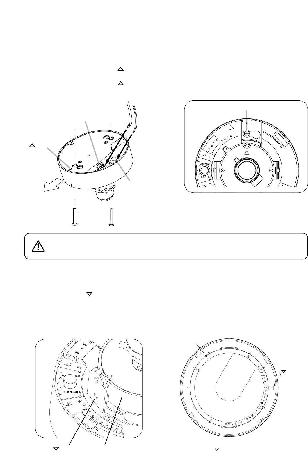
Camera output terminal
Coaxial cable
Power supply
cable
Power input
terminal
Camera direction
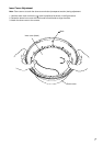
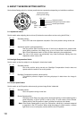
Rotate the inner cover to the "R" range,
and align the mark with scale indicator "3."
Inner cover
mar
k
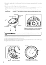
Mounting screws
Note
Ensure that the mounting screws are set securely
in their corresponding camera mounting holes.
Be sure to use the optional ceiling bracket whenever the ceiling panel
material seems too weak to securely mount the camera.
WARNING
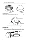
4. Adjust the camera’s angle of view and focus, then attach the dome cover.
4-1. Align the camera head assembly with the inner cover.
Note the position of the mark on the camera head assembly (indicated in the figure as "3" in the "R" range),
and align the camera’s scale with that of the inner cover.
mark Camera head assembly
2. Connect the coaxial cable to the Video output Terminal, and the power supply cable to the Power Input
Terminal.
3. Mount the camera to the ceiling or wall using 2 mounting screws.
Because the mounting screws are not supplied with the camera, prepare appropriate screws for the
application. (Use screws that are over 4 mm in nominal diameter and longer than 25 mm.)
Ceiling mounting : Orient the mark located on the camera’s bottom surface toward the direction in
which the camera is to be pointed.
Wall mounting : Orient the mark located on the camera’s bottom surface up (toward the ceiling).