


IK-6420A
1-4
- 9 -
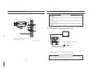
6. LENS
Back-Focus Adjusment
Back-Focus is adjusted at the factory to accommodate most standard lenses.
Sometimes, slight adjustment to the camera back-focus is
necessary.
Loosen the Focus Lock Screw. Achieve a clear image by
rotating the focus ring.
Tighten the Focus Lock Screw.
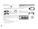
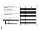
Auto-iris Lens
This camera supports two types of auto-iris lens: Video
and DC (direct drive) types. Connect the auto-iris
connector plug to the IRIS terminal on the side of the
camera. Refer to the chart below for correct wiring and
set up.
Video IRIS Direct Drive
Lens IRIS Lens
1 +12V Damp – (y)
2NC Damp + (γ)
3 VIDEO Driver + (wh)
4 GND Driver – (g)
IRIS Switch VIDEO position DC position
IRIS terminal
pin
Focus Lock Screw
Focus ring
IRIS
Auto-iris lens
43
21
Camera Side
- 8 -
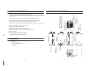
5-2. Line-Lock Control
• Matching the vertical synchronization with the power frequency is called the Line-Lock.
• This function is activated when the LL switch is set to ON.
LL
ON
OFF
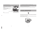
• When two or more cameras are switched by the video switcher for viewing by a monitor TV, the
vertical sync. phase can be locked to the power frequency, and a stable vertical sync. is obtained
without being disturbed at the time of switching.
CAMERA1
CAMERA2 VIDEO SWITCHER
TO 24V AC UL Listed
Class 2 power supply
MONITOR TV
Note:
• The camera is synchronized to the power frequency of 60 ±1 Hz covering a normal fluctuation of
the power frequency. However, the camera may not cover a large fluctuation caused from the
power generated by an engine generator, etc.
•It takes about 10 seconds or more until a stable synchronization is obtained after the power is
turned on. This is normal, because several seconds are required to stabilize the camera against
power noise.
• Refer to "7. LINE-LOCK PHASE" for adjustment.
5-3. Operation
1. Mount the lens to the camera.
2. Mount the camera to the camera mount.
Caution: If the lens weight is more than 2.2 lbs (1 kg) mount the lens to the camera mount.
Refer to section 6 for lens types and connection.
3. Connect the cables and support equipment to obtain a picture.
4. Adjust the lens aperture (if applicable).