


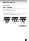

14
A
A
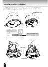
Wall Mount
Ceiling Mount
1414
Notes:
l
The included screws and anchors are used to install the
camera to a solid surface. (e.g. concrete) If installing on loose
or thin material surfaces , use the appropriate anchors (not
included) with the screws.
l
If possible, point the TOSHIBA logo towards the eld of
view. The adjustment range of PAN is indicated on the
alignment sticker.
l
Install the camera securely.
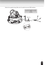
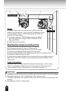
Mounting the camera to a solid surface
(1) Attach the Alignment Sticker to the surface.
(2) Drill two pilot holes (Ø0.20inch×0.99inches(D)
(Ø5mmX25mm(D))) through the two circles on the sticker.
(3) Hammer the supplied plastic anchors into the holes.
(4) Drill a cable hole A(Ø1.1inch (Ø28mm)) as shown in the above picture ,
and lead the cables through this hole.
(5) Align the two mounting holes of the Camera with the two plastic anchors;
insert the included two screws to the corresponding holes and tighten them
with a driver.
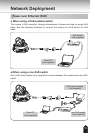
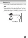
Cable installation
If possible, lead all cables behind the camera body through a wall or ceiling.
If this is not possible, use the knock out on the camera cover to route the
cables through the side. (Please refer to Completion on page 21.)
CAUTION
l
Installation should be done only by qualied personnel and conform to all local codes.
l
Install this camera on a rm and solid part of the ceiling or wall.
If installed improperly or on a weak surface, the camera could fall causing injury and
damage.
l
Use Category (Cat) 5 or higher cable.