


T
T
T
S
S
S
1
1
1
6
6
6
G
G
G
~
~
~
6
6
6
4
4
4
G
G
G
C
C
C
F
F
F
4
4
4
0
0
0
0
0
0
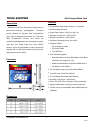
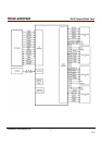
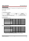
400X CompactFlash Card
Transcend Information Inc.
V1.0
7
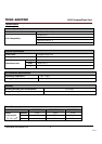
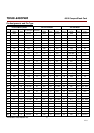
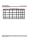
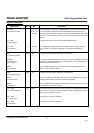
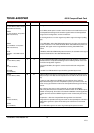
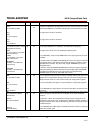
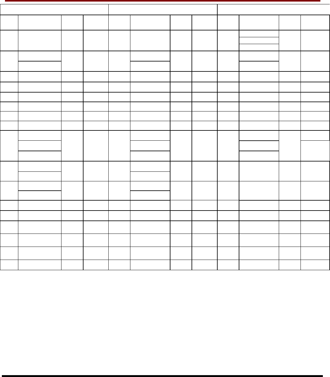
PC Card Memory Mode PC Card I/O Mode True IDE Mode
4
Pin
Num
Signal Name
Pin
Type
In, Out
Type
Pin
Num
Signal Name
Pin
Type
In, Out
Type
Pin
Num
Signal Name
Pin
Type
In, Out
Type
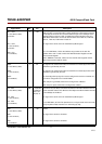
-HIOE
7
HSTROBE
8
34
-HIOE
HSTROBE
10
HDMARDY
11
I I3U 34
-HIOE
HSTROBE
10
-HDMARDY
11
I I3U 34
-HDMARDY
9
I I3Z
-IOWR -IOWR -IOWR
7
35
STOP
10,11
I I3U 35
STOP
10,11
I I3U 35
STOP
8,9
I I3Z
36
-WE I I3U 36 -WE I I3U 36 -WE
3
I I3U
37
READY O OT1 37 -IREQ O OT1 37 INTRQ O OZ1
38
VCC Power
38 VCC Power
38 VCC Power
39
-CSEL
5
I I2Z 39 -CSEL
5
I I2Z 39 -CSEL I I2U
40
-VS2 O OPEN
40 -VS2 O OPEN
40 -VS2 O OPEN
41
RESET I I2Z 41 RESET I I2Z 41 -RESET I I2Z
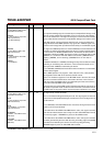
-WAIT -WAIT IORDY
7
ON1
-DDMARDY
10
-DDMARDY
10
-DDMARDY
8
42
DSTROBE
11
O OT1 42
DSTROBE
11
O OT1 42
DSTROBE
9
O
OT1
13
-INPACK -INPACK
43
-DMARQ
12
O OT1 43
-DMARQ
12
O OT1 43 DMARQ O OZ1
-REG I I3U 44 -REG
44
-DMACK
12
DMACK
12
I I3U 44 -DMACK
6
I I3U
45
BVD2 O OT1 45 -SPKR O OT1 45 -DASP I/O I1U, ON1
46
BVD1 O OT1 46 -STSCHG O OT1 46 -PDIAG I/O I1U, ON1
47
D08
1
I/O
I1Z,
OZ3
47 D08
1
I/O
I1Z,
OZ3
47 D08
1
I/O
I1Z, OZ3
48
D09
1
I/O
I1Z,
OZ3
48 D09
1
I/O
I1Z,
OZ3
48 D09
1
I/O
I1Z, OZ3
49
D10
1
I/O
I1Z,
OZ3
49 D10
1
I/O
I1Z,
OZ3
49 D10
1
I/O
I1Z, OZ3
50
GND Ground
50 GND Ground
50 GND Ground
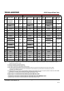
Note: 1) These signals are required only for 16 bit accesses and not required when installed in 8 bit systems. Devices should allow for 3-state
signals not to consume current.
2) The signal should be grounded by the host.
3) The signal should be tied to VCC by the host.
4) The mode is required for CompactFlash Storage Cards.
5) The -CSEL signal is ignored by the card in PC Card modes. However, because it is not pulled upon the card in these modes,
it should not be left floating by the host in PC Card modes. In these modes, the pin should be connected by the host to PC
Card A25 or grounded by the host.
6) If DMA operations are not used, the signal should be held high or tied to VCC by the host. For proper operation in older hosts: while DMA
operations are not active, the card shall ignore this signal,including a floating condition
7) Signal usage in True IDE Mode except when Ultra DMA mode protocol is active.
8) Signal usage in True IDE Mode when Ultra DMA mode protocol DMA Write is active.
9) Signal usage in True IDE Mode when Ultra DMA mode protocol DMA Read is active.
10) Signal usage in PC Card I/O and Memory Mode when Ultra DMA mode protocol DMA Write is active.
11) Signal usage in PC Card I/O and Memory Mode when Ultra DMA mode protocol DMA Read is active.
12) Signal usage in PC Card I/O and Memory Mode when Ultra DMA protocol is active.