


T
T
T
S
S
S
2
2
2
G
G
G
~
~
~
8
8
8
G
G
G
C
C
C
F
F
F
2
2
2
6
6
6
6
6
6
266X CompactFlash Card
Transcend Information Inc.
16
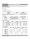
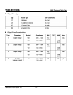
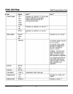
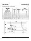
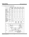
Table: Ultra DMA Termination with Pull-up or Pull down Example
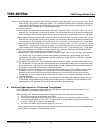
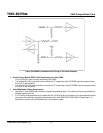
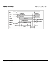
¾ Printed Circuit Board (PCB) Trace Requirements for Ultra DMA
On any PCB for a host or device supporting Ultra DMA:
9 The longest D[15:00] trace shall be no more than 0.5" longer than either STROBE trace as measured from
the IC pin to the connector.
9 The shortest D[15:00] trace shall be no more than 0.5" shorter than either STROBE trace as measured from
the IC pin to the connector.
¾ Ultra DMA Mode Cabling Requirement
9 Operation in Ultra DMA mode requires a crosstalk suppressing cable. The cable shall have a grounded line
between each signal line.
9 For True IDE mode operation using a cable with IDE (ATA) type 40 pin connectors it is recommended that the
host sense the cable type using the method described in the ANSI INCITS 361-2002 AT Attachment - 6
standard, to prevent use of Ultra DMA with a 40 conductor cable.