


Hi-Res. B/W camera instruction manual
ADC 660N and ADC 660P
_________________________________
11
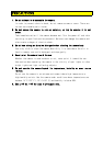
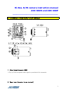
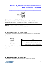
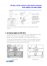
7. AGC ON/OFF Switch
This switch is provided for the AGC circuit. The AGC circuit incorporated into the
camera boosts the sensitivity automatically when the scene illumination is
insufficient.
8. INT/LL Switch (LL is ON; INT is OFF)
This camera can operate independently, using its internal crystal-controlled sync
generator, or it may be synchronized using line-locking.
To select one or the other of these sync modes, set the DIP switch on the rear
panel to either INT or LL. Switch 4 is set to ON for LL and OFF for INT.
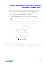
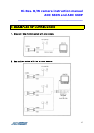
If line-lock is selected, all the cameras in the system must be adjusted to begin the
video field scan at the same time. This is described in procedure
⑩
.
9.
FL ON Switch (Flickerless ON/OFF)
This function is only used in JAPAN. In order to use FL mode, set EE/AI
switch to AI first and then FL ON/OFF switch to ON.
When the DIP switch on the rear panel is set to ON, the shutter speed is
fixed at a rate of 1/100(120)(sec).
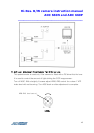
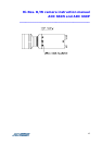
10. V-Phase Adjustment Potentiometer
This potentiometer is set full counter clockwise at the factory. If two or
more cameras are connected to a switcher and the picture on the monitor rolls
while switching from camera A to B, adjusting the vertical phase (V-phase) of
the cameras will probably eliminate the rolling. If this adjustment is
necessary, it should only be performed by a qualified technician. Before
making any adjustment, confirm that cameras A and B are connected to the
power supply with the same polarity.
To make an adjustment, follow the steps below.