


VIVOTEK - A Leading Provider of Multimedia Communication Solutions
User's Manual - 5
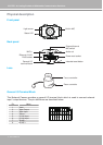
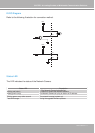
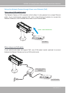
DI/DO Diagram
Refer to the following illustration for connection method�
12V
+12V
Digital output
PIN 1
Power+12V
PIN 2
Digital input
PIN 3
Ground
PIN 4
Status LED
The LED indicates the status of the Network Camera�
Status LED Description
Blinking red (short)
1� The Network Camera is booting up�
2� Reboot or restore the Network Camera�
Steady green (long) The Network Camera is trying to obtain an IP address�
Blinking green every other second The network is setup (system up)�
Fast blink orange During the upgrade firmware process�