


VIVOTEK
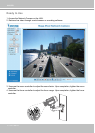
User's Manual - 9
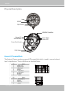
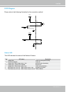
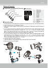
Waterproof Connector
1 Power +12V
2 Digital Output
3 Digital Input
4 Ground
5 AC 24V
6 AC 24V
7 RS485 +
8 RS485 -
1 External MIC In
2 Ground
3 Audio Out
4 Ground
87654321
4321
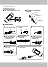
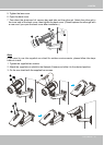
1� Disassemble the components of the waterproof connector into part (A) ~ (E) as shown above�
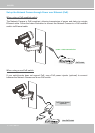
2� Open the back cover of the Network Camera�
3� Remove the rubber stopper from the bottom of the Network Camera and secure the screw nut
(A) tightly�
4� If you need extra power for external devices, please feed the power cable through the wall
mount bracket and the waterproof connector (E --> D --> B --> A) as the illustration shown
below� Then connect the power cord to the socket� Note: There are 7 holes on the seal (B),
and the widest hole with a crack on the side is specic for power cord.
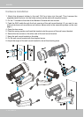
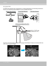
5� If you have external devices such as sensors and alarms, feed the cables through the wall
mount bracket and the waterproof connector (E --> D --> B --> A) as the illustration shown
below. Then refer to the pin denition to connect them to the general I/O terminal block. Note:
The recommended cable gauge is 2�0 ~ 2�8 mm�
6� Push the seal (B) into the housing (D)�
7� Insert the seals (C) into the empty holes on the seal (B) to avoid moisture�
8� Secure the sealing nut (E) tightly�
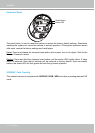
Components of the Waterproof Connector
Seals (C)
Housing (D)
Sealing Nut (E)
Seal (B)
Screw Nut (A)
Pin Denition
Assembling Steps
3
4
(E)
(D)
(B)
(A)
5
4
7
6
8
(C)
(B)
(D)
(E)