


VIVOTEK
8 - User's Manual
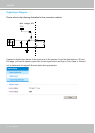
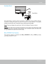
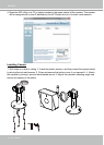
Digital Input Diagram
Please refer to the following illustration for the connection method�
3.3V
Digital input
DI+
DI-: Ground
DI-
Max. voltage: 40V
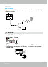
Connect a digital input device to the input pins of the camera� From the Applications > DI and
DO page, you can let camera report the current signal status as High or Low, Open or Ground-
ed, to determine the signal’s Normal status during operation�