


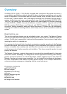
VIVOTEK - A Leading Provider of Multimedia Communication Solutions
User's Manual - 5
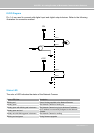
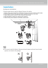
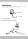
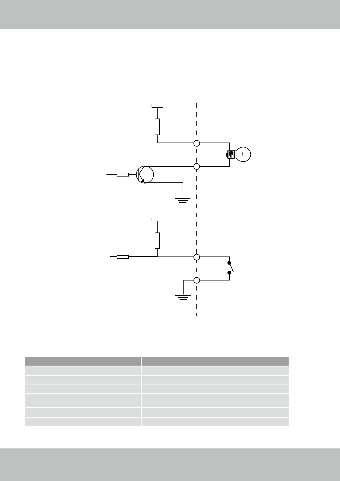
DI/DO Diagram
Pin 1~4 are used to connect with digital input and digital output devices� Refer to the following
illustration for connection method�
12V
+12V
Digital output
PIN 1
Power+12V
PIN 2
Digital input
PIN 3
Ground
PIN 4
Status LED
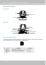
The color of LED indicates the status of the Network Camera�
Status LED Color Description
Blinking red Power is being supplied to the Network Camera.
Steady green The Network Camera is booting up.
Steady green with blinking red in between The Network Camera is trying to obtain an IP address.
Steady green and red
An IP address is successfully assigned to the Network
Camera.
Steady red with blinking green in between The Network Camera is working.
Blinking red and green During firmware upgrade