


ENGLISH
MSR250 Owner’s Manual
5
Thank you for purchasing the Yamaha MSR250 powered speaker.
The development of this powered speaker is a natural extension of Yamaha’s extensive experience and
knowledge of PA devices. The MSR250 faithfully reproduces sound for a wide range of applications. Please
read this manual thoroughly to make the best use of the MSR250 for the longest possible period of time. Keep
the manual in a safe place for future reference.
A
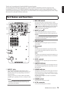
INPUT 1 jacks
These balanced XLR/phone jacks connect a micro-
phone, mixer, or electronic musical instrument, etc. Set
the MIC/LINE switch (
2
) depending on the level of
the input signal.
XLR-type connectors are wired as follows (IEC60268
standard): pin 1: ground, pin 2: hot (+), and pin 3: cold
(–).
NOTE:
You may use either the XLR or the phone jack, but not
both types simultaneously. Please connect to only one
type of jack on the channel.
B
MIC/LINE switch
Set this switch to MIC or LINE for INPUT 1 jacks,
depending on the level of the input signal. For low-level
signals (such as microphones), set the switch to the MIC
( ) position. For high-level signals (such as electronic
musical instruments and audio equipment), set the
switch to the LINE ( ) position.
C
INPUT 2/3 jacks
These unbalanced phone/RCA pin jacks connect an
electronic musical instrument or audio equipment, etc.
NOTE:
You may use either the phone or RCA pin jacks, but not
both types simultaneously. Please connect to only one
type of jack on each channel.
D
LINK OUT jack
This outputs the mixed signals input via the INPUT1
and 2/3 jacks.
E
EQ controls
HIGH:
The HIGH control adjusts the output level at 10kHz
over a ±6 dB range. Rotate clockwise to boost or coun-
terclockwise to cut.
LOW:
The LOW control adjusts the output level at 60Hz over a
±3 dB range. Rotate clockwise to boost or counterclock-
wise to cut.
F
LEVEL controls
Determine the level of signals input from the INPUT1
or 2/3 jacks.
G
LIMITER indicator
This lights up if the output level is too high. In this case,
lower the level using the LEVEL controls (
6
) or lower
the input level.
H
POWER Indicator
This lights up when the power switch (
9
) is turned on.
When the protection circuit is activated due to overcur-
rent or heat, the output will be muted, with the POWER
indicator remaining lit.
Turn the power on again if you hear no sound after
waiting a while.
I
POWER switch
This switch turns the power on/off.
J
AC IN connector
Connect the included power cord here.
Part Names and Functions
9
8
7
6
1
3
4
2
J
5