14
Advanced Operations
About PRO DJ LINK
When a PRO DJ LINK-compatible Pioneer DJ player (CDJ-2000, CDJ-900 etc.),
a computer on which rekordbox is installed and this unit are connected by LAN
cable, the PRO DJ LINK functions below can be used.
For more details on the PRO DJ LINK function, also refer to the DJ player’s han-
dling instructions and rekordbox’s operating instructions.
For instructions on connections, see Connecting input terminals on page 7.
! Up to four DJ players can be connected. Up to two computers can be
connected.
! Connect the DJ players to the [LINK] terminal ([CH1] to [CH4]) with the same
number as the channel to which the audio cables are connected.
! Connect the computers to the [COMPUTER 1] or [COMPUTER 2] terminal.
SD & USB Export
rekordbox music files and management data on SD memory cards/
USB devices
connected to a CDJ-2000, CDJ-900, etc., can be transferred between DJ players.
rekordbox LINK Export
This function lets you transfer rekordbox music files and management data
directly, eliminating the bother of exporting the data to an SD memory card/
USB
device.
LIVE SAMPLER
The sound input to the [MIC] terminal or output from the [MASTER] terminals
can be sampled and played on a DJ player.
LINK MONITOR
With this function, rekordbox music files stored on the computer can be quickly
monitored over the headphones.
STATUS INFORMATION
This function informs the DJ players of the connected channel status (on-air
status, channel number, etc.).
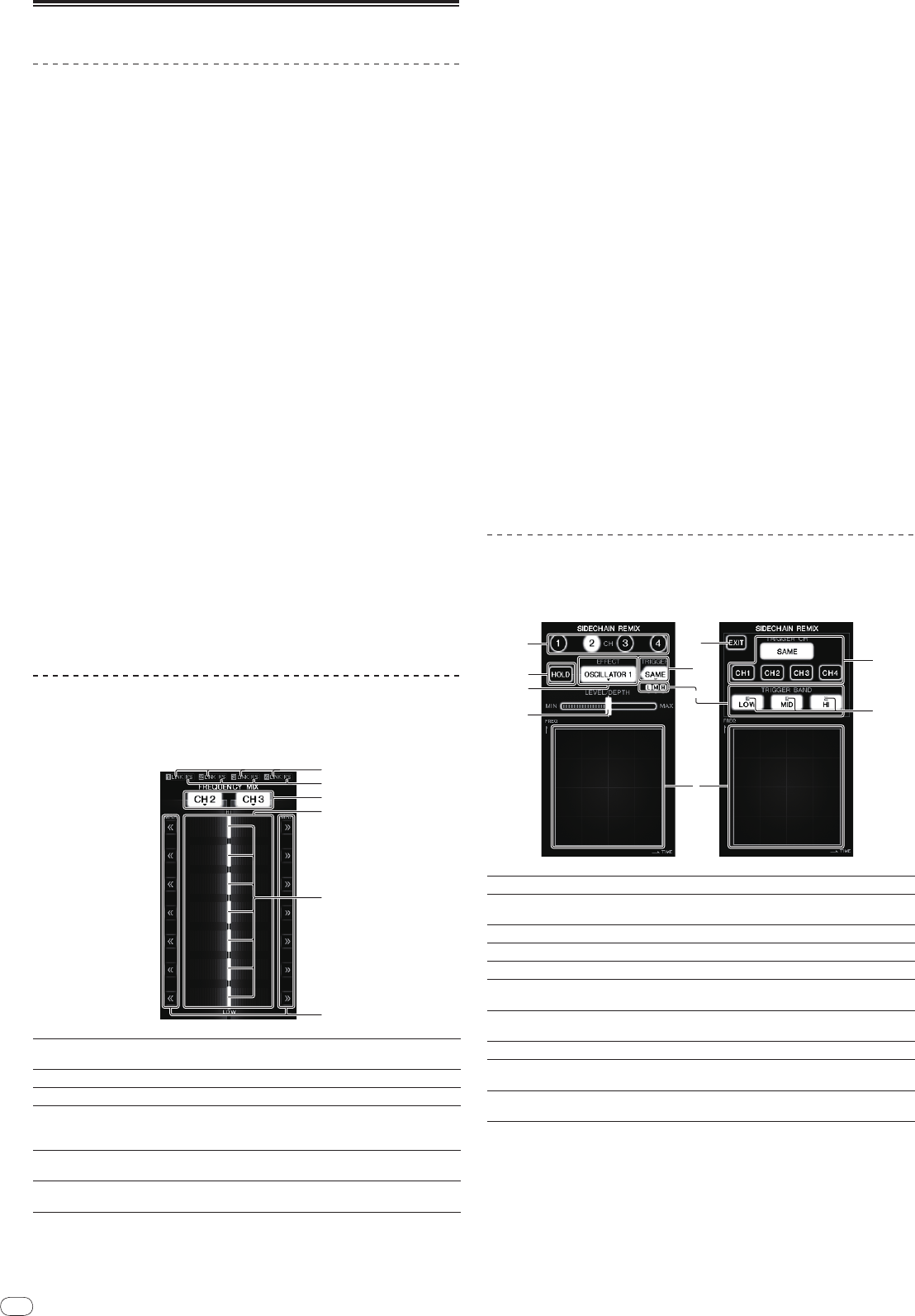
FREQUENCY MIX
The currently playing sound is divided into seven frequency bands that are dis-
played graphically. Fader control on the touch panel makes it easier to grasp the
details and mix two channels or swap instruments (parts).
1
LINK
These light when DJ players are properly connected to the
[LINK] terminals.
2
FS
These light when the fader start function is turned on.
3
Channel assign buttons These select the channels to be mixed.
4
Volume level display
The input volume level to this function is displayed in a light
color, the output volume level from this function is displayed
in a dark color.
5
Touch fader
These adjust the volume balance of the channels to be
mixed for the separate frequency bands.
6
<< >>
These move the touch fader immediately to the left or right
edge.
To mix [CH2] and [CH3]:
Prepare this unit in advance so that the sound of [CH3] is being output from the
[MASTER] terminals.
1 Set the [CROSS FADER ASSIGN (A, THRU, B)] switches for [CH2]
and [CH 3] to [THRU].
! Set the [CROSS FADER ASSIGN (A, THRU, B)] switches of the channels to be
mixed to [THRU].
! When using the crossfader, it is recommended to set it to the center position.
2 Press [MIX].
The [FREQUENCY MIX] screen appears on the touch panel.
3 Press the channel assign buttons to select [CH2] for the left
side, [CH3] for the right side.
The volume levels for the individual frequency bands of the sound playing in
[CH3] are displayed on the right half of the touch panel.
4 Press all the [ >> ] buttons.
All the touch faders move to the right edge.
5 Press [ON/
OFF].
This turns the effect on.
[ON/
OFF] flashes when the effect is turned on.
6 Move the channel fader for [CH2] to the back side.
The volume levels for the individual frequency bands of the sound playing in
[CH2] are displayed on the left half of the touch panel.
7 Move the touch fader to the left side.
The sound of the frequency bands whose crossfaders have been moved is mixed
and output.
! The effect turns off when [ON/
OFF] is pressed again.
! To switch from the [FREQUENCY MIX] to the [SIDECHAIN REMIX] mode, first
press the [ON/
OFF] button to turn the effect off, then press [REMIX].
SIDECHAIN REMIX
When this function is used, the sound of the specified frequency band for the
specified channel can be used as the trigger to apply effects to the sounds of
other channels.
1
CH
This selects the channel to which the effect is applied.
2
HOLD
This holds the effect’s parameter information (the position
at which the control area was touched).
3
EFFECT
This selects the type of effect.
4
LEVEL/
DEPTH
Use this to adjust the amount of the effect applied.
5
EXIT
Use this to close the [TRIGGER] menu.
6
TRIGGER (SAMPLING/
TRIGGER)
Use this to open the [TRIGGER] menu.
7
TRIGGER BAND
Use these to select the frequency band to be used as the
trigger.
8
Control area Use this to change the effect’s parameters.
9
TRIGGER CH (SAM-
PLING/
TRIGGER CH)
This selects the channel to be used as the effect trigger.
a
Trigger indicators
These flash according to the automatically detected rhythm
for the different frequency bands.
To set the channel for sampling and triggering to [CH3]
and mix the sampled sound with the sound of [CH2] for
output:
Prepare this unit in advance so that the sound of [CH2] is being output from the
[MASTER] terminals.
1 Press [REMIX].
The [SIDECHAIN REMIX] screen appears on the touch panel.
