© 2011 Schneider Electric. All Rights Reserved.
63230-500-225A2 PowerLogic
TM
Series 800 Power Meter
3/2011 Chapter 6—Alarms
45
Chapter 6—Alarms
This section describes the alarm features on all Series 800 Power Meters. For information
about advanced alarm features, go to “Advanced Alarms” on page 53.
Basic Alarms
The power meter can detect over 50 alarm conditions, including over or under conditions,
digital input changes, phase unbalance conditions, and more. It also maintains a counter
for each alarm to keep track of the total number of occurrences. A complete list of default
basic alarm configurations are described in Table 6–5 on page 51 . In addition, you can set
up your own custom alarms after installing an input/output module (PM8M22, PM8M26, or
PM8M2222).
When one or more alarm conditions are true, the power meter will execute a task
automatically. When an alarm is active, the
! alarm icon appears in the upper-right corner
of the power meter display. If a PM810LOG is installed on a PM810, PowerLogic software
can be used to set up each alarm condition to force data log entries in a single data log file.
For the PM820, PM850, and PM870 PowerLogic software can be used to set up each
alarm condition to force data log entries in up to three user-defined data log files. See
Chapter 7—Logging on page 57 for more about data logging.
NOTE: PM820 only supports one data log.
Basic Alarm Groups
When using a default alarm, you first choose the alarm group that is appropriate for the
application. Each alarm condition is assigned to one of these alarm groups:
Whether you are using a default alarm or creating a custom alarm, you first choose the
alarm group that is appropriate for the application. Each alarm condition is assigned to one
of these alarm groups:
• Standard—Standard alarms have a detection rate of 1 second and are useful for
detecting conditions such as over current and under voltage. Up to 40 alarms can be
set up in this alarm group.
• Digital—Digital alarms are triggered by an exception such as the transition of a digital
input or the end of an incremental energy interval. Up to 12 alarms can be set up in this
group.
• Custom—The power meter has many pre-defined alarms, but you can also set up your
own custom alarms using PowerLogic software. For example, you may need to alarm
on the ON-to-OFF transition of a digital input. To create this type of custom alarm:
1. Select the appropriate alarm group (digital in this case).
2. Select the type of alarm (described in Table 6–6 on page 52 ).
3. Give the alarm a name.
4. Save the custom alarm.
After creating a custom alarm, you can configure it by applying priorities, setting pickups
and dropouts (if applicable), and so forth.
Both the power meter display and PowerLogic software can be used to set up standard,
digital, and custom alarm types.
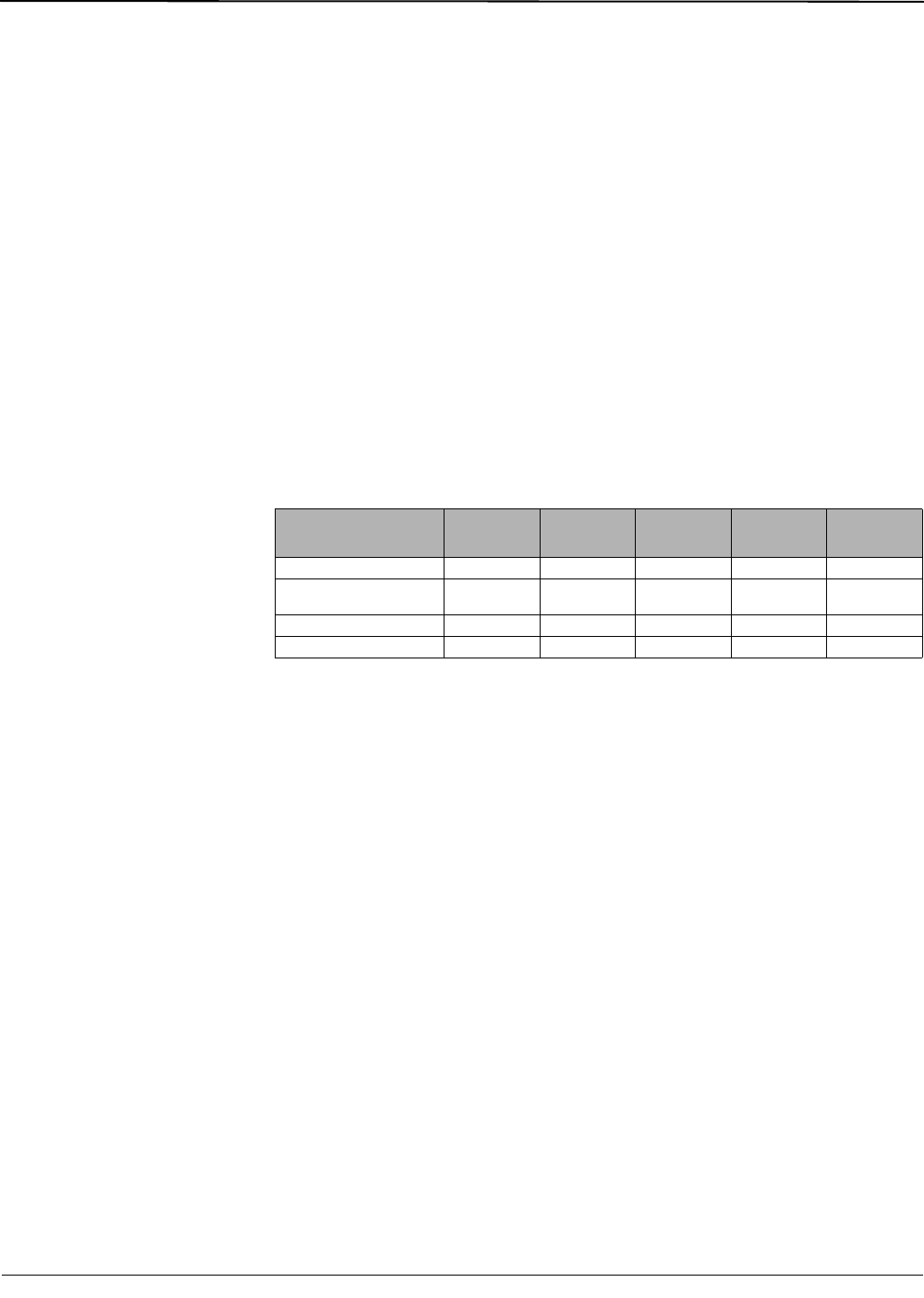
Table 6–1: Basic alarm features by model
Basic Alarm Feature PM810
PM810 with
PM810LOG
PM820 PM850 PM870
Standard alarms 33 33 33 33 33
Open slots for additional
standard alarms
7
➀
7
➀
777
Digital 12
➁
12
➁
12
➁
12
➁
12
➁
Custom alarms No No Yes Yes Yes
➀ Available when an I/O module with analog IN/OUT is installed.
➁ Requires an input/output option module (PM8M22, PM8M26, or the PM8M2222).
