© Titan Tool Inc. All rights reserved. 35
Hydra M™ & Hydra Pro Super™ Fluid Accessories
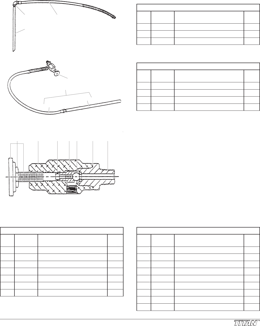
840-209 Bleed Line Assembly
ITEM
NO.
PART
NO.
DESCRIPTION QTY.
1 944-028 Valve, bleed 1
2 103-101 Bleed line assembly 1
3 0509764 Tube (1)
4 538-030 Hose assembly (1)
103-106 Bleed Line Assembly
ITEM
NO.
PART
NO.
DESCRIPTION QTY.
1 103-317 Tube 1
2 201-555 Elbow 1
3 538-031 Hose assembly 1
4
3
2
1
2
1
3
944-620 Bleed Valve Assembly, 1/8” NPT
ITEM
NO.
PART
NO.
DESCRIPTION QTY.
1 944-024 Knob assembly 1
2 944-020 Valve body 1
3 944-004 O-ring 1
4 944-026 Valve stem stop 1
5 761-715 Ball, T.C. 1
6 945-003 Gasket, copper 1
7 944-904 Valve seat 1
945-600 Bleed Valve Assembly, 1/2” NPT
ITEM
NO.
PART
NO.
DESCRIPTION QTY.
1 945-005 Knob 1
2 970-011 Nut 1
3 944-023 Valve stem 1
4 945-022 Valve body 1
5 891-073
O-ring, PTFE
1
6 944-026 Valve stem stop 1
7 138-2269 Ball 1
8 891-183
O-ring, PTFE
1
9 945-906 Valve seat 1
1 2 3 4 5 6 7
Service Instructions
The 944 / 945 Series Relief Valve has a tungsten carbide seat
(9) and should not require frequent replacement. The tungsten
carbide ball (7), in normal service, will last a long time because it
rotates and wears evenly. If there is leakage, replace the ball.
IMPORTANT: Open the adjustment knob (1) to full
counterclockwise position before unthreading valve seat (9)
from valve body (4).
If the valve stem (3) is rotated inwardly with the ball removed,
the PTFE O-ring (5) may require replacement. If there has
been leakage from the valve stem, the PTFE O-ring should be
replaced.
IMPORTANT: The valve stem stop (6) must be unthreaded
from the valve stem (3) with a socket screwdriver, then the
valve stem can be threaded out of the valve body.
IMPORTANT: All non-moving threads must be assembled
with Loctite sealant, Titan part # 426-051.
Part No. 944-600
