© Titan Tool Inc. All rights reserved. 9
Maintaining the Engine
When transporting a sprayer with a gas engine,
make sure the fuel is shut off.
NOTE: For detailed engine specications and
maintenance, refer to the separate engine
manual supplied with this sprayer.
Important Facts Concerning this Sprayer
This gas-powered sprayer contains a clutch that engages when
the sprayer is pumping. The sprayer’s pressure control system
engages and disengages the clutch to control pressure. To
prevent unnecessary wear to the clutch, it is advisable to adjust
the engine speed and pressure setting to limit the amount of
times the clutch engages and disengages. To reduce clutch
wear, refer to the following examples.
Example:
Operating one gun with a .019 tip — reduce the engine speed
by adjusting the throttle to a low or medium setting and increase
pressure only until the heavy ends of the spray pattern have
been eliminated.
Example:
Operating one gun with .023 tip — increase engine speed to a
higher setting and increase pressure until the heavy ends of the
spray pattern have been eliminated.
Example:
Spraying light-bodied materials at low pressure — to reduce
surging at the gun and to decrease clutch wear, reduce the
engine speed to idle and reduce pressure until the desired spray
pattern is achieved.
Routine Engine Maintenance
Daily
• Check and ll the gas tank.
• After the rst 20 hours of operation, drain the oil and
rell with clean oil. Check the engine oil level and ll as
necessary.
Weekly
• Remove the cover of the air lter and clean the element.
Replace the element if necessary. If operating in an
unusually dusty environment, check the lter daily and
replace if necessary. (Replacement elements can be
purchased from your local Titan dealer.)
• After each 50 hours of operation: Change the engine oil.
Spark Plug
• Use only a (NKG) BP6ES plug.
• Gap the plug 0.025” – 0.030” (0.7 – 0.8 mm).
• Make sure to use a spark plug wrench when installing and
removing the plug.
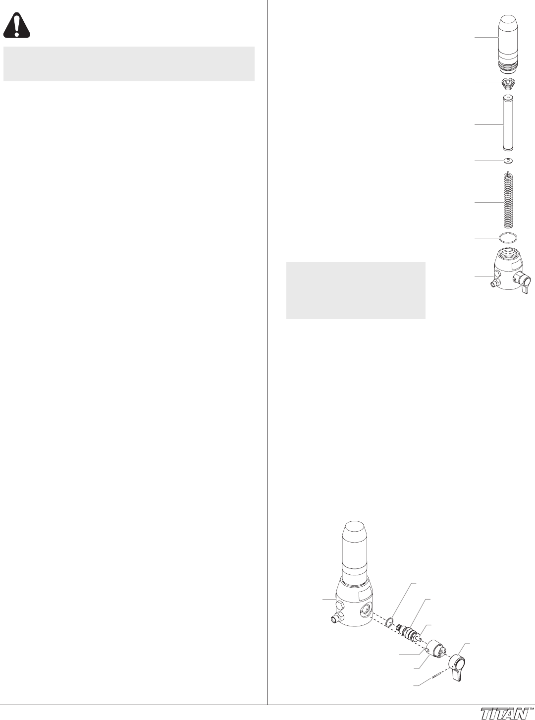
Replacing the Filter
Filter
Spring
Filter
Body
Filter
Support
Spring
Filter
Adapter
Filter
Housing
O-ring
Filter
Housing
1. Loosen and remove the lter
body by hand.
2. Remove the lter and lter
support spring spring from the
lter housing.
3. Remove the lter support spring
and adapter from inside the lter.
4. Inspect the lter. Based on
inspection, clean or replace the
lter.
5. Inspect the lter housing o-ring.
Based on inspection, clean or
replace the o-ring.
6. Slide the new or cleaned lter
over the adapter and lter
support spring. Place the lter
and lter support spring into the
center of the lter housing.
7. Clean the inside of the lter
body.
8. Slide the lter body over the
lter and thread it into the lter
housing until secure. Make sure
the lter spring is in position on
top of the lter.
NOTE: The lter body should
be hand-tightened,
but make sure it is
seated fully into the
lter housing.
Replacing the PRIME/SPRAY Valve
Perform the following procedure using PRIME/SPRAY valve
replacement kit P/N 0507690.
1. Drive the groove pin out of the valve handle.
2. Remove the valve handle and the cam base.
3. Using a wrench, loosen and remove the valve housing
assembly.
4. Make sure the gasket is in place and thread the new valve
housing assembly into the lter housing. Tighten securely
with a wrench.
5. Place the cam base over the valve housing assembly.
Lubricate the cam base with grease and line up the cam
with the lter block using the dowel pin.
6. Line up the hole on the valve stem with the hole in the
valve handle.
7. Insert the groove pin into the valve handle and through the
valve stem to secure the valve handle in position.
Dowel Pin
Cam Base
Valve Stem
Filter
Housing
Valve Housing
Assembly
Gasket
Groove Pin
Valve Handle
