English
2 ©TitanToolInc.Allrightsreserved.
Specications
Maximum operating pressure ........................3900PSI(27MPa)
Materialinletthreadsize ..................................NPSM1/4”
Diuserthreadsize .............................................7/8-14UNF-2A
Wettedpartsmaterial ........................................High-gradestainlesssteel,
urethane,polyethylene,
nylon,hardmetal
Operatingtemperaturerange ........................40ºFto104ºF(5ºCto40ºC)
Maximum material temperature ...................109ºF(43ºC)
Maximum sound output ...................................81dB(A)*
Weight ...............................................................1.3lbs.(590g)
* Measurementlocation:1.5’awayfromthecoatingsurface,1.5’behind
thespraygun,spraypressure1700PSI,tipsize0.021”
Using the Gun Trigger Lock
Alwaysengagethegun’striggerlockwhenthegunisnotinuse.
1. Tolockthetrigger,rotatethetriggerlockbackwarduntilitstops.
2. Tounlockthetrigger,rotatethetriggerlockforwarduntilitisvertical.
Trigger locked
Tr
igger unlocked
(gun will spray)
Setup
Never attempt to assemble, change, or clean the gun, tip,
or tip guard without first relieving pressure from the spray
system. Follow the “Pressure Relief Procedure” in the
sprayer’s Owner’s Manual.
Always use a tip safety guard for added protection against
injection. Beware that the guard alone will not prevent
injection. Never cut off tip guard! Always engage gun trigger
lock when the gun is not in use. Before servicing equipment,
consult Owner’s Manuals and follow all warnings.
1. Setupthesprayer.Refertotheinstructionsinthesprayer’sOwner’s
Manual.
2. Attachagrounded,airlesssprayhosetothematerialinletonthegun.
Usingtwowrenches(oneonthegunandoneonthehose),tighten
securely.
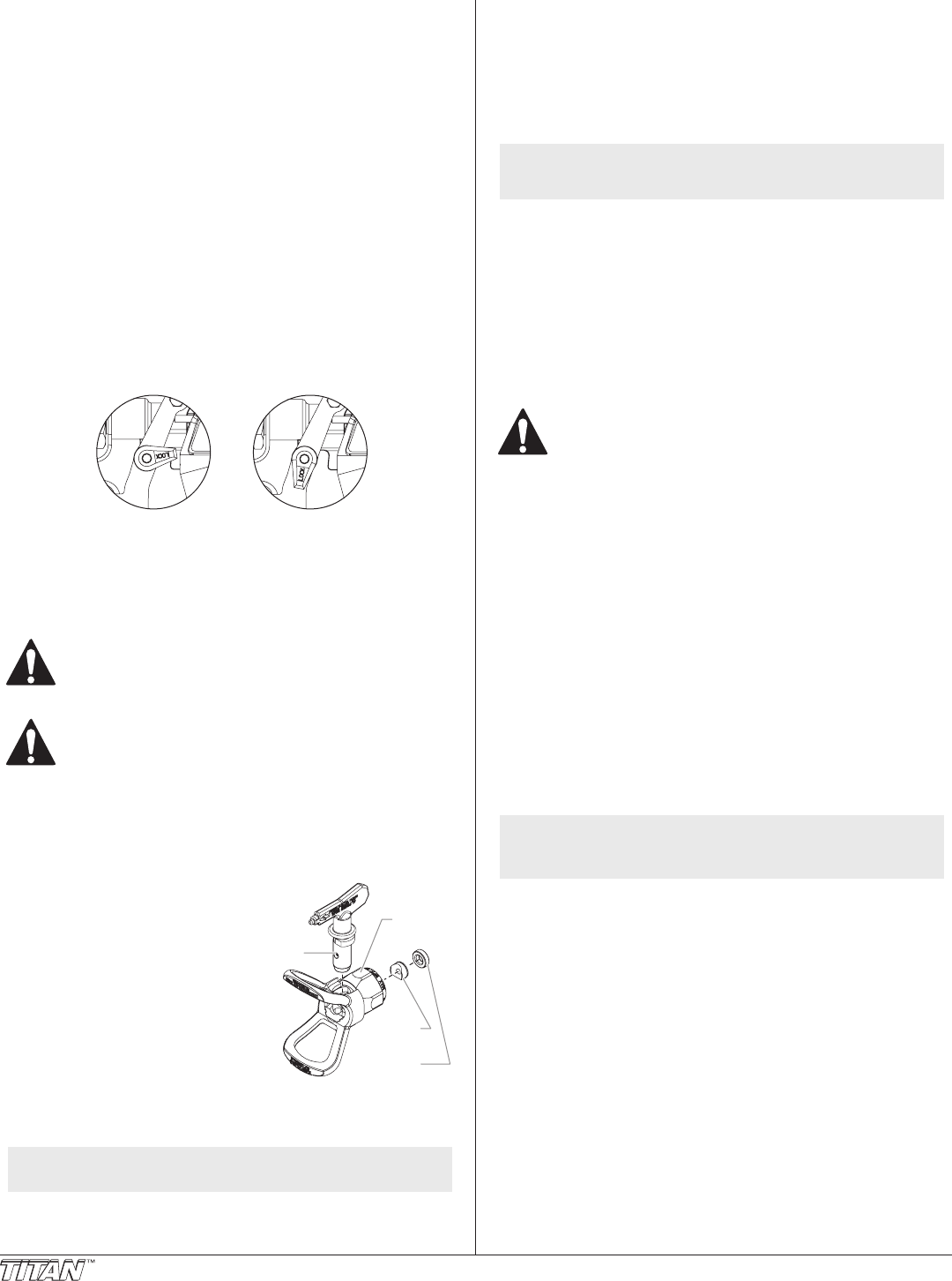
Tip Seal
Retainer
Tip Seal
ip
Tip Guard
3. Withthetipandtipguardothegun,
startthesprayer.Flushandprepare
the spray system according to the
sprayer’sOwner’sManual.Inspect
the spray system to make sure that all
ttings are secure and that there are
no leaks.
4. Performthe“PressureRelief
Procedure”describedinthesprayer’s
Owner’sManual.
5. Usingthearrowheadonthetip
handle,insertthetipsealandtipseal
retainerintothebackofthetipguard.
Press in for nal adjustment.
6. Insertthetipintotheslotonthetipguard.
7. Threadthetipguardontothegun.Positionthetipguardinthe
desired spraying position and tighten securely.
NOTE: The arrow on the tip handle should be pointing in the
forward direction for spraying.
Operation
1. Make sure the arrow on the tip handle is pointing in the forward
direction for spraying.
2. Startthesprayer.Refertotheinstructionsinthesprayer’sOwner’s
Manual.
3. Adjusttheuidpressureonthesprayeruntilthesprayiscompletely
atomized.Alwayssprayatthelowestpressurenecessarytogetthe
desired results.
NOTE: The spray tip determines the size of spray pattern and
coverage. When more coverage is needed, use a larger tip
instead of increasing uid pressure.
4. Toclearacloggedtip:
a. Rotatethetip180ºsothatthearrowonthetiphandleis
pointing opposite the spray direction.
b. Triggerthegunoncesothatthepressurecanblowtheclogout.
IMPORTANT: Never pull the trigger more than once at time with the tip
in the reverse position.
c. Continuethisprocedureuntilthetipisclearoftheclog.
Changing a Tip
Tipscanberemovedandreplacedeasilywithoutdisassemblingthegun.
Never attempt to change or clean the tip or tip guard without
first performing the “Pressure Relief Procedure.”
1. Performthe“PressureReliefProcedure”describedinthesprayer’s
Owner’sManual.
2. Removethetipfromtheslotonthetipguard.
3. Insertthenewtipintotheslotonthetipguard.Thearrowonthetip
handleshouldbepointingintheforwarddirection.
Removing the Seal and Tip Seal
1. Removethetipandtipguardfromthespraygun.
2. Removethesealandtipsealfromthebackofthetipguard.
Identifying Tip Sizes
Toidentifytipsizes,usethefollowingformula.A“517”tipsizewillbeusedin
this example.
Therstdigitmultipliedbytworepresentsthesizeofthespraypatternwhen
spraying12”awayfromtheworksurface:
5x2=10”spraypattern
Thesecondtwodigitsrepresentthediameteroftheoriceonthetip:
17=.017”orice
NOTE: Worn spray tips will adversely aect the spray pattern
and result in reduced production, poor nish, and wasted
material. Replace worn tips immediately.


