


Lexicon, Inc.
DC-2/MC-1 Serial Communications Protocol Printed on: 10/19/00
6 of 44
5.3 Errors
The DC-2/MC-1 will detect parity, framing and data overrun errors. If an error is detected by the DC-
2/MC-1, the DC-2/MC-1 will transmit an NAK packet with a error code of: DC_ERR_PARTIY,
DC_ERR_FRAME, DC_ERR_OVER, corresponding to the error detected. If any of the physical layer
errors are detected, the complete packet is corrupted and the DC-2/MC-1 will reset the transaction and
begin to look for a start of packet byte.
All Error codes are listed in Appendix B Error Codes.
5.4 DC-2/MC-1 Receive Buffer
The DC-2/MC-1 has an internal receive buffer. The buffer is 256 Bytes and will transmit a NAK packet
with an error code of DC_ERR_BUFFER_FULL to the HOST if the buffer is full. If the buffer is full, all
data transmitted to the DC-2/MC-1 will be ignored. Therefore, making the currently transmitted packet, if
partially transmitted invalid.
5.5 DC-2/MC-1 Hardware Verification
This test verifies the RS232 ports are working by comparing the transmitted signal (at pin 2) to the received
signal (at pin 3) . The DC-2/MC-1 transmits a know test signal just following a power up. The DC-2/MC-1
monitors the serial port receivers while transmitting the test signal. If the signals are the same, the test
passes. In order to test this circuit, (1 for Dc-2 and 2 for MC-1) RS232 Wraparound plug(s) are needed and
must be installed at the female D9 connector(s) on the rear panel of the DC-2/MC-1/SDP-3 labeled
“RS232”. The wraparound plug shorts pins 2 to 3, allowing for the MC-1 to receive the signal it is
transmitting. Once installed, power cycle the DC-2/MC-1/SDP-3 and verify the following message is
displayed on the VFD about 20 seconds after power up:
SERIAL PORT A PASSED
SERIAL PORT B PASSED
This message is displayed for about 2 seconds before entering normal operating mode. If either or both
messages are not displayed, the test failed.
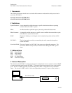
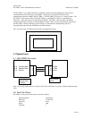
6 Data Link Layer
The data link layer is used to define a transmission packet. The layer appends a header and tail that
encloses the transmitted application packet data. The data link header will contain the start of packet byte
and count of bytes to follow. The data link tail will contain the end of packet byte.