Controls in detail, continued
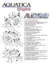
19. REAR VIEW DISPLAY WINDOW: allow viewing of menu and images
20. PLAYBACK ZOOM BUTTON / QUALITY: Press to activate the zoom function while reviewing your images in playback mode or
use to select image and/or size quality in shooting mode.
21. THUMBNAIL BUTTON / ISO: Press to display images in “contact sheets” of 4 or 9 images in playback mode or to select ISO
value in shooting mode.
22. HELP / PROTECT BUTTON / WHITE BALANCE: Press to access the help function or to protect selected image from accidental
deletion in playback mode or to access white balance in shooting mode.
23. MENU BUTTON: Press to activate menu, use multi selectors buttons (17) to navigate, press OK button (18) to choose a
selection.
24. PLAYBACK BUTTON: Press to activate the monitor and review images or to select image and/or size quality.
25. DELETE / FORMAT BUTTON: Press to delete images, use multiple selector buttons to select and press the enter button to
delete. Use in conjunction with (27) to format your card.
26. MODE DIAL CONTROL KNOB: rotate clockwise or counter clockwise to select the shooting mode, manual, shutter or aperture
priority and auto program options.
27. METERING MODE / FORMAT BUTTON: Push to select the metering mode, Spot, Center-Weighted or Matrix metering options.
Use in conjunction with (25) to format your card.
28. EXPOSURE COMPENSATION / RESET BUTTON: press to engage the Exposure compensation control [+/-]. Rotate the
Main-Command knob to set the desired exposure compensation value. The value will appear in the Top LCD panel and in the
Viewnder. This button when pressed at the same time as the AF mode Selector button (13) will reset the camera settings to its
default position.
29. TOP LCD WINDOW: displays essential camera operating data.
30. MOUNTING HOLE: These are 1/4-20 TPI holes that are ready to accept TLC Base Brackets or TLC Base Ball for strobe arms
or accessories.
31. MODE DIAL WINDOW: Gives you visual contact with the mode dial for selection of the proper shooting mode.
32. GRIPS MOUNTING HOLES: Two 1/4” X 20 holes are provided on each grip for mounting strobes trays or accessories.
33. RUBBER ANTISKID PAD: four rubber pads are provided to prevent the housing from skidding on wet surface.
34. MOUNTING HOLES FOR TRAY: Two 1/4”-20 TPI holes are supplied to accept mounting tray and accessories.
35. SACRIFICIAL ANODES: (2X) zinc anodes are installed to protect your housing against salt water corrosion; theses are made
to deteriorate easier than the other strategic part of your housing, hence the name sacricial anodes. These anodes will need to be
replaced as needed.


