


RING
TEL
TEL
BAL
MIC
GND
RING
CONTACT
ALC
TEL VOLUME
MIC VOLUME
+
BAL
T
R
TEL
MIC
COM
LO
C
K
LOCK
CONTROLS
MUSIC IN
BRIDGING
APHEX
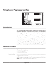
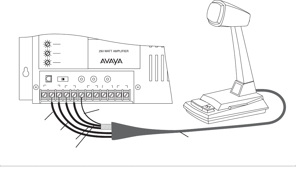
White - MIC ‘CONTROLS’
Green - COM ‘CONTROLS’
Red - MIC + ‘MIC BAL’
Black - MIC - ‘MIC BAL’
Microphone
Cable
Shield - GND
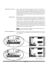
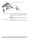
Tel Input to Universal Coupler After properly connecting your Universal Coupler (909) to your auxiliary trunk
port, set your switches as follows: C1/C2 to C2; Rocker Switch 3 closed; and all
others open. Coming out of the J2 Jack of the Coupler, connect the blue/white pair
to the amplifier Tip and Ring. Connect the brown/white pair to Tel and Com on the
control terminals.
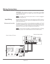
Music Input A single RCA connector is provided for the connection of a background music
source. Use a male RCA-to-RCA cable (not included) to make this connection. This
is a mono input and requires that the output of stereo sources be converted to
mono by using a Y-adapter (not included). Use a LUWMT1A to balance the music
input, if necessary,to reduce hum/noise from a grounded music source.
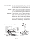
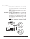
Microphone Input A high gain, low impedance microphone input is provided in this amplifier. It is
designed to work with microphone LUSZMIC (Com Code: 408186238, PEC Code:
5335-400). Connect the microphone's black wire to the amplifier's "-" (negative)
terminal under the MIC BAL connections. Connect the microphone’s Red wire to
the "+" (positive) terminal. Connect the shield wire from the microphone to the
adjacent GND terminal. Connect the microphone's white lead to the Control
terminal marked MIC and the green lead to the COM. (See Figure 5.)
Two conductor shielded microphone wire should be used to extend the cable from
the microphone. 22 AWG shielded, twisted pair speaker cable (Com Code:
401882956, PEC Code: 2734-SPK) will also work. When extending microphone
cable, be sure to connect the shields of the microphone cable to the extension wire.
Page 7 of 12
Figure 5: Connect Microphone to Telephone Paging Amplifier