


Page 6 AXIS 209FD/FD-R/FD-R M12/MFD/MFD-R/MFD-R M12 Installation Guide
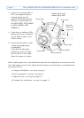
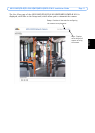
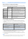
4. Connect the network cable. If
PoE is not supported by the
network switch, use the
supplied PoE midspan/power
injector to connect power to
the AXIS 209FD, AXIS 209FD-
R, AXIS 209MFD, AXIS
209MFD-R.
5. Check that the indicator LED:s
indicate the correct conditions.
See the table on page 15 for
further details.
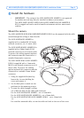
6. Fasten the base plate to a flat
ceiling, using appropriate
screws/plugs.
Check that the base plate
completely covers the cable
hole, so that it is not visible
when the camera is in place.
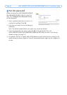
Before replacing the cover, you should now make the final adjustment to the position of the
lens. This requires access to live images from the camera in your browser, so you should now
proceed as follows:
a) Assign an IP address - see step 4 on page 7.
b) Set the password - see step 5 on page 10.
c) Adjust the lens - see step 6 on page 12.
d) Complete the installation - see step 7 on page 13.
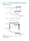
Network
cable with
connector
Indicator LEDs
Screw hole
Screw hole
Screw hole
Product ID & Serial
number (S/N) label
Screw hole
Control button