


AXIS M1054 Network Camera
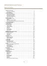
Hardware Overview
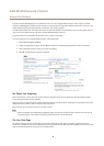
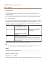
Hardware Overview
9
6
7
3
4
5
1
8
11
12
13
14
2
10
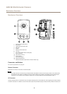
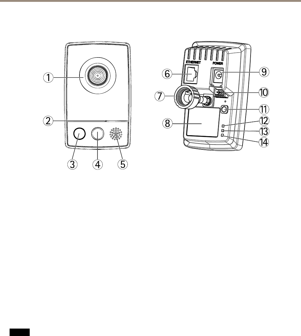
1
Lens with Status LED indicator
2
Microphone
3
Light (white illumination LED)
4
PIR sensor
5
Speaker
6
Network connector (RJ-45)
7
Lock ring
8
Part number (P/N) & Serial number (S/N)
9
Power connector
10
I/O terminal connector
11
Control button
12
Power LED indicator
13
Network LED indicator
14
Wireless LED indicator (activated on wireless models only)
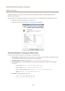
Connectors and Buttons
For technical specications, see page 57.
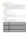
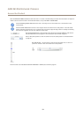
Network Connector
RJ45 Ethernet connector with Power over Ethernet (PoE).
NONO
NO
TICETICE
TICE
The product shall be connected using a shielded network cable (STP). All cables connecting the product to the network shall
be intended for their specic use. Make sure that the network devices are installed in accordance with the manufacturer’s
instructions. For information about regulatory requirements, see Electromagnetic Compatibility (EMC) on page 2 .
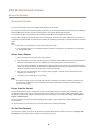
I/O Connector
Use with external devices in combination with, for example, tampering alarms, motion detection, event triggering, time lapse recording
and alarm notications. In addition to the 0 V DC reference point and power (DC output), the I/O connector provides the interface to:
6