


AXIS P1214 Network Camera
Hardware Overview
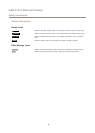
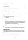
Hardware Overview
10
11
98
7
321
654
12
13
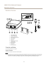
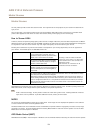
1
Power indicator LED
2
Status indicator LED
3
Network indicator LED
4
SD card slot (microSD card)
5
RJ12 connector
6
I/O connector
7
Main unit
8
Network connector (PoE)
9
Control button
10
Power connector
11
Mounting rail
12
Sensor unit
13
Mounting bracket
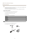
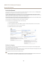
Connectors and Buttons
For technical specications, see page 51.
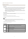
Network Connector
RJ45 Ethernet connector with Power over Ethernet (PoE).
NONO
NO
TICETICE
TICE
The product shall be connected using a shielded network cable (STP). All cables connecting the product to the network shall
be intended for their specic use. Make sure that the network devices are installed in accordance with the manufacturer’s
instructions. For information about regulatory requirements, see Electromagnetic Compatibility (EMC) on page 2 .
6