


AXIS P1214 Network Camera
Hardware Overview
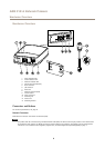
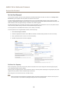
I/O Connector
Use with external devices in combination with, for example, tampering alarms, motion detection, event triggering, time lapse recording
and alarm notications. In addition to the 0 V DC reference point and power (DC output), the I/O connector provides the interface to:
• Digital output – For connecting external devices such as relays and LEDs. Connected devices can be activated by the
VAPIX® Application Programming Interface, output buttons on the Live View page or by an Action Rule. The output will
show as active (shown under System Options > Ports & Devices) if the alarm device is activated.
• Digital input – An alarm input for connecting devices that can toggle between an open and closed circuit, for example:
PIRs, door/window contacts, glass break detectors, etc. When a signal is received the state changes and the input becomes
active (shown under System Options > Ports & Devices).
Power Connector
2-pin terminal block for power input. Use a Safety Extra Low Voltage (SELV) compliant limited power source (LPS) with either a rated
output power limited to ≤100 W or a rated output current limited to ≤5 A.
RJ12 Connector
The RJ12 connector is used for connecting the sensor unit to the main unit.
For information on how to shorten the sensor unit cable see Shorten Sensor Unit Cable on page 8 .
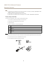
SD Card Slot
NONO
NO
TICETICE
TICE
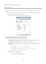
• Risk of damage to SD card. Do not use sharp tools or excessive force when inserting or removing the SD card.
• Risk of data loss. To prevent data corruption, the SD card should be unmounted before removal. To unmount, go to Setup >
System Options > Storage > SD Card and click Unmount.
This product supports microSD/microSDHC/microSDXC card (not included).
For SD card recommendations, see www.axis.com
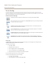
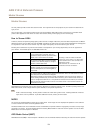
LED Indicators
LED
Color
Indication
Green
Steady for connection to a 100 MBit/s network. Flashes for network activity.
Amber
Steady for connection to a 10 MBit/s network. Flashes for network activity.
Network
Unlit No network connection.
Green Steady green for normal operation.
Amber
Steady during startup and when restoring settings.
Red
Slow ash for failed upgrade.
Status
Unlit No connection between sensor unit and main unit.
Green
Normal operation.
Power
Amber
Flashes green/amber during rmware upgrade.
7