


AXIS P12 Series Installation Guide Page 9
ENGLISH
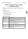
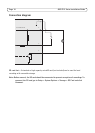
Connectors
Network - RJ45 Ethernet connector. Supports PoE (Power over Ethernet, class 2).
Due to local regulations or the environmental and electrical conditions in which the product is
to be used, a shielded network cable (STP) may be appropriate or required. Any network cables
that are routed outdoors or in demanding electrical environments shall be shielded (STP) and
intended for their specific use. Make sure the network switch is properly grounded. See
Electromagnetic Compatibility (EMC) for regulatory requirements.
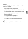
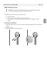
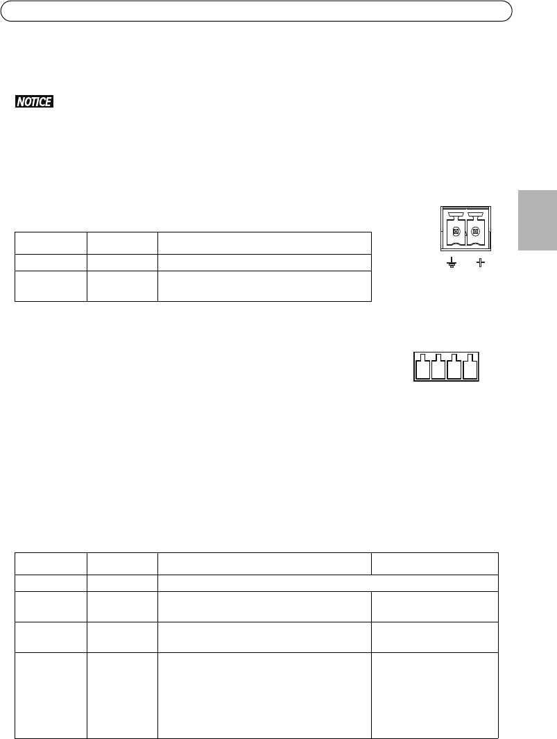
Power connector - 2-pin terminal block for power input.
Camera connector - RJ12 connector.
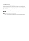
I/O terminal connector - Use in applications for e.g. motion detection,
event triggering, time lapse recording and alarm notifications. In addition
to an auxiliary power and a GND pin, the I/O terminal connector provides
the interface to:
• Digital output — For connecting external devices such as relays and LEDs. Connected
devices can be activated by the VAPIX® Application Programming Interface, output buttons
on the Live View page or by an Action Rule. The output will show as active (shown under
System Options > Port & Devices > Port Status) if the alarm device is activated.
• Digital input — An alarm input for connecting devices that can toggle between an open and
closed circuit, for example: PIRs, door/window contacts, glass break detectors, etc. When a
signal is received the state changes and the input becomes active (shown under System
Options > Port & Devices > Port Status).
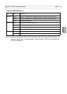
Function Pin number Description
GND 1 Ground
DC Power 2 Power input 8-28 V DC
max 4.7 W
Function Pin number Notes Specifications
GND 1 Ground
3.3 V DC
Power
2 Can be used to power auxiliary equipment.
Note: This pin can only be used as power out.
Max load = 50 mA
Input 3 Digital input - Connect to GND to activate, or
leave floating (or unconnected) to deactivate.
0 to +40 V DC
Output 4 Digital output - Internal connection to
ground when activated, floating
(unconnected) when deactivated. If used
with an external relay, a diode must be
connected in parallel with the load, for
protection against voltage transients.
Max load = 100 mA
Max voltage = +40 V DC
1
2
1 2 3 4