


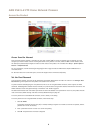

AXIS P5415–E PTZ Dome Network Camera
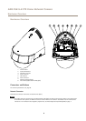
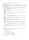
Hardware Overview
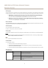
I/O Connector
Use with external devices in combination with, for example, tampering alarms, motion detection, event triggering, time lapse recording
and alarm notications. In addition to the 0 V DC reference point and power (DC output), the I/O connector provides the interface to:
• Digital output – For connecting external devices such as relays and LEDs. Connected devices can be activated by the
VAPIX® Application Programming Interface, output buttons on the Live View page or by an Action Rule. The output will
show as active (shown under System Options > Ports & Devices) if the alarm device is activated.
• Digital input – An alarm input for connecting devices that can toggle between an open and closed circuit, for example:
PIRs, door/window contacts, glass break detectors, etc. When a signal is received the state changes and the input becomes
active (shown under System Options > Ports & Devices).
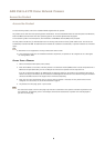
Power Connector
2-pin terminal block for power input. Use a Safety Extra Low Voltage (SELV) compliant limited power source (LPS) with either a rated
output power limited to ≤100 W or a rated output current limited to ≤5 A.
Audio Connector
4-pin terminal block for audio input and output.
For audio in, the left channel is used from a stereo signal.
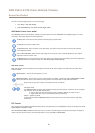
SD Card Slot
An SD card (not included) can be used for local recording with removable storage. For more information, see Technical Specications.
NONO
NO
TICETICE
TICE
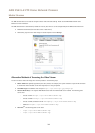
To prevent corruption of recordings, the SD card should be unmounted before removal. To unmount, go to Setup > System
Options > Storage > SD Card and click Unmount.
Note
For SD card recommendations see www.axis.com
Control Button
The control button is used for:
• Resetting the product to factory default settings. See page 55.
• Connecting to an AXIS Video Hosting System service. See page 48. To connect, press and hold the button for about 3
seconds until the Status LED ashes green.
• Connecting to AXIS Internet Dynamic DNS Service. See page 48. To connect, press and hold the button for about 3 seconds.
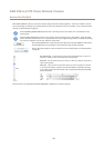
LED Indicators
LED
Color
Indication
Unlit
Connection and normal operation
Amber
Steady during startup. Flashes during rmware upgrade.
Amber/red Flashes amber/red if network connection is unavailable or lost.
Red Flashes red for rmware upgrade failure.
Status
Green Shows steady green for 10 seconds for normal operation after startup is
completed.
7