


AXIS Q1604-E Network Camera
Technical Specifications
Connectors
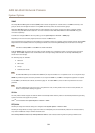
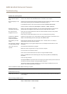
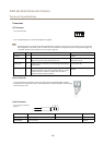
I/O Connector
4-pin terminal block
1 2 3 4
For an example diagram, see Connection Diagrams on page 68.
Note
The I/O connector is connected to the housing (fan/heater) on delivery. In the case of a fan or heater error, an input signal
will be triggered in the camera. Set up an action rule in the camera to congure which action the signal shall trigger. For
information about events and action rules, see Events on page 39.
Function Pin Notes
Specications
0 V DC (-)
1
0 V DC
DC output
2
Can be used to power auxiliary equipment.
Note: This pin can only be used as power out.
3.3 V DC
Max load = 50 mA
Digital input
3
Connect to pin 1 to activate, or leave oating (unconnected)
to deactivate
0 to max 40 V DC
Digital output
4
Connected to pin 1 when activated, oating (unconnected)
when deactivated. If used with an inductive load, e.g. a relay,
a diode must be connected in parallel with the load, for
protection against voltage transients.
0 to max 40 V DC, open drain,
100 mA
Power Connector
2-pin terminal block for DC power input. Use a Safety Extra Low Voltage (SELV) compliant
limited power source (LPS) with either a rated output power limited to ≤100 W or a rated output
current limited to ≤5 A.
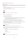
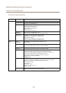
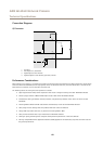
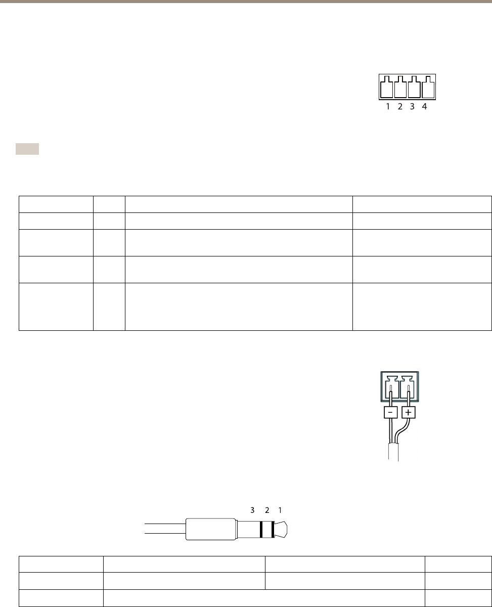
Audio Connector
3.5 mm audio connectors
(stereo)
123
1 Tip 2 Ring
3 Sleeve
Audio Input
Microphone/Line in
Ground
Audio Output
Line out (mono)
Ground
67