


AXIS T8123-E/T8124-E Installation Guide Page 7
ENGLISH
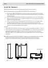
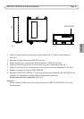
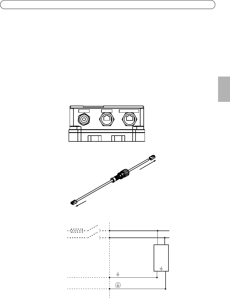
3. Thread male plug waterproof connector cover (A,B and C) on to the Ethernet cable. See Fig 3.
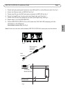
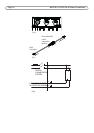
4. Attach the Ethernet cable to DATA IN. See Fig 2.
5. Thread plug (A) over the RJ45 male plug, connected to DATA IN. See Fig 3.
6. Thread housing (B) over the plug and screw (hand tight only). See Fig 3.
7. Thread cover (C) over the connector and screw (hand tight only). See Fig 3.
8. Repeat steps 2 to 6 for DATA PWR OUT.
9. Connect AXIS T8123-E/T8124-E to an AC power line (100-240 V AC) complying with the
information in the Safeguards.
International version only. See Fig 4.
Note: Do not use cross over cable between AXIS T8123-E/T8124-E output port and load device.
DATA IN
DATA PWR OUT
LINE AC
L
N
N
PE
L
PE
Fig 2
Fig 3
RJ45
male plug
A
B
C
RJ45 male plug
waterproof
connector
cover
Fig 4
INCOMING
MAINS VOLTAGE
EXTERNAL PROTECTIVE
GROUND WIRE